
Universal Broadband Router Hardware Installation Guide


5-9
Cisco uBR10012 Universal Broadband Router Hardware Installation Guide
OL-18259-01
Chapter 5 Maintaining the Cisco uBR10012 Router
Removing and Replacing DC Power Entry Modules
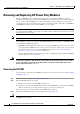
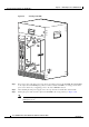
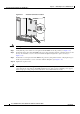
Step 4 (Optional) Turn off the DC power source that is providing power for this DC PEM. All LEDs on the DC
PEM should turn off. (This step is required only if you need to rewire the terminal block for this PEM,
as described in step
6.)
Tip Separate DC power sources should be used for each DC PEM. This allows you to turn off the power
source for the DC PEM being replaced without affecting the power source for the online DC PEM.
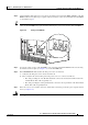
Figure 5-6 Turning a DC PEM Off
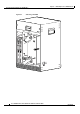
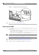
Step 5 Loosen the captive screws on the DC PEM you are removing and pull the PEM from the chassis using
the handles on the faceplate (see
Figure 5-7). Set the DC PEM aside.
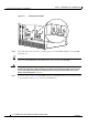
Step 6 If the MISWIRE LED indicated that the DC power source is miswired,
a. Verify that the DC power source has been turned off.
b. Then verify that the wires leading to the DC power source are connected as follows:
–
The cable providing the –48/–60 VDC should be connected to the bottom terminal on the DC
terminal block. This cable is typically red.
–
The cable providing the return path should be connected to the top terminal on the DC terminal
block. This cable is typically black.
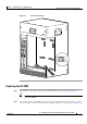
Step 7 If the wires were reversed when connected, switch them so that they provide the power signals as listed
above (see
Figure 5-8).
Warning
Use copper conductors only.
Statement 1025
56461
ALARM
S
FAIL
PERFORMANCE ROUTING ENGINE
STATUS
ACO
CRITICAL
MINOR
MAJOR
ALA
RMS
FAIL
PERFORMANCE ROUTING ENGINE
STATUS
ACO
C
RITICAL
MINOR
MAJOR
OFF
OFF
OFF