
Universal Broadband Router Hardware Installation Guide


5-8
Cisco uBR10012 Universal Broadband Router Hardware Installation Guide
OL-18259-01
Chapter 5 Maintaining the Cisco uBR10012 Router
Removing and Replacing DC Power Entry Modules
Removing and Replacing DC Power Entry Modules
The Cisco uBR10012 router is shipped with two DC power entry modules (PEM) that provide a
redundant power supply to the system. One DC PEM can provide sufficient power for a fully configured
chassis, so that if one DC PEM fails, the other automatically begins providing power for the entire
system. However, the system should not be run for an extended period time with only one DC PEM. If
a DC PEM fails, install a replacement DC PEM as soon as possible.
Note You do not need to shut down the Cisco uBR10012 router to replace a redundant DC PEM. And, if you
are replacing both DC PEMs, you can replace one, bring it online, and then replace the other one to avoid
shutting down the entire system.
Note The product order number for a replacement DC PEM is UBR10-PWR-DC=.
The DC PEM is operating correctly when its POWER LED lights (green). Replace a DC PEM if either
of the PEM failure LEDs light (yellow):
• MISWIRE—This LED indicates that the wires connecting the PEM to DC power source were wired
incorrectly. The DC PEM therefore needs to be removed so that the wiring can be corrected. After
the wiring has been corrected, the same DC PEM can be reinserted. See
“Connecting Alarm
Indicators” section on page 5-18 for more information.
• FAULT—This LED indicates that the DC power source is supplying power but that the DC PEM is
not providing power to the system.ced.
Warning
Before performing any of the following procedures, ensure that power is removed from the DC circuit.
To ensure that all power is OFF, locate the circuit breaker on the panel board that services the DC
circuit, switch the circuit breaker to the OFF position, and tape the switch handle of the circuit
breaker in the OFF position.
Statement 7
Removing the DC PEM
Do not use this procedure if both DC PEMs have failed; instead, use the next procedure, Replacing Both
DC PEMs, page 5-13.
Step 1 Remove the front cover (see “Removing the Front Cover”).
Step 2 If the FAULT LED light in on (yellow):
a. Flip the power switch on the DC PEM off and then on.
b. If this does not turn off the FAULT LED and turn on the POWER LED, verify that the DC PEM is
fully inserted into the power bay and that its captive screws have been tightened.
If these steps do not correct the problem, the DC PEM must be replaced.
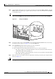
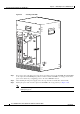
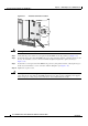
Step 3 Turn off the DC PEM, the switch is in the off (0) position (see Figure 5-6).
Caution Do not power off both DC PEMs, or the system shuts down and all data traffic stops. Turn off only the
DC PEM you are replacing.