
Universal Broadband Router Hardware Installation Guide


5-7
Cisco uBR10012 Universal Broadband Router Hardware Installation Guide
OL-18259-01
Chapter 5 Maintaining the Cisco uBR10012 Router
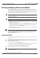
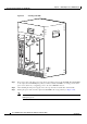
Removing and Replacing the Fan Assembly Module
Caution The Cisco uBR10012 chassis should not be run without a working fan assembly module for more than
three minutes. To prevent the possibility of the system overheating, be sure that the replacement fan
assembly module is out of its box and packaging, so it is ready to install as soon as the defective module
is removed.
Step 1 Remove the front cover (see “Removing the Front Cover”).
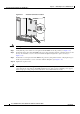
Step 2 Loosen the captive screws on each side of the fan assembly module and use two hands to pull the module
out of the chassis (see
Figure 5-5).
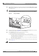
Figure 5-5 Removing the Fan Assembly Module
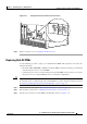
Caution The fan assembly module weighs approximately 30 pounds. Use one hand to pull the fan assembly
module using its handle and position the other hand underneath the module to support it, so that it does
not suddenly swing down when it clears the chassis.
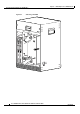
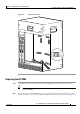
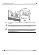
Step 3 Using two hands, align the new fan assembly module in the slot on the chassis and push it back firmly,
making sure it securely connects to the backplane.
Step 4 Verify that the FANS OK LED lights (green). If the FANS OK LED does not light or if either fan failure
LED lights (yellow), try reseating the fan assembly module.
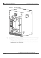
Step 5 Tighten the captive screws on each side of the fan assembly module.
Step 6 Replace the front cover (see “Replacing the Front Cover”).
56293
CISCO
10000
CISCO