
Universal Broadband Router Hardware Installation Guide

5-6
Cisco uBR10012 Universal Broadband Router Hardware Installation Guide
OL-18259-01
Chapter 5 Maintaining the Cisco uBR10012 Router
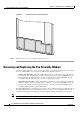
Removing and Replacing the Fan Assembly Module
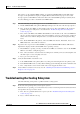
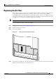
Figure 5-4 Air Filter Inserted into the Front Cover
Step 5 Replace the front cover (see “Replacing the Front Cover”).
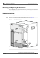
Removing and Replacing the Fan Assembly Module
The fan assembly module does not need to be replaced when it is operating normally. However, if either
of the two failure LEDs come on, the fan assembly module should be replaced:
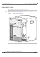
• SINGLE FAN FAILURE—This yellow LED indicates that one of the four fans in the module has
failed. The module can still provide enough cooling to safely operate the Cisco uBR10012 chassis,
but it might begin operating the fans in its high-speed mode to do so. If this LED lights, the fan
assembly module should be replaced as soon as is conveniently possible.
• MULTIPLE FAN FAILURE—This yellow LED indicates that two or more fans in the module have
failed, and that the module is no longer able to consistently cool the Cisco uBR10012 chassis. To
prevent overheating the chassis and possible damage to the line cards and other modules, the fan
assembly module should be replaced immediately.
If a failure LED lights, use the following procedure to remove and reinsert the fan assembly module. If
the failure LED is still on, use the following procedure to replace the fan assembly module. The fan
assembly module supports hot-swapping and can be replaced without interrupting system operation.
Note The product order number for a replacement fan assembly is UBR10-FAN-ASSY=.
56392