
Universal Broadband Router Hardware Installation Guide

3-51
Cisco uBR10012 Universal Broadband Router Hardware Installation Guide
OL-18259-01
Chapter 3 Installing the Cisco uBR10012 Router
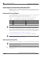
Connecting the Console Port and Auxiliary Port
Connecting to the Auxiliary Port
The auxiliary port provides a connection for a modem to allow remote access to the router and its
command-line interface (CLI).
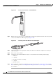
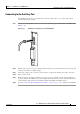
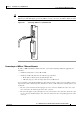
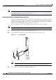
Step 1 Connect one end of the RJ-45 crossover cable to the serial RJ-45 port (labelled AUX) on the PRE module
(
Figure 3-41).
Figure 3-41 Auxiliary Port Connection on the PRE Module
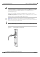
Step 2 Run the other end of the crossover cable through the square hole at the left front side of the chassis, and
connect it to the RJ-45-to-DB-25 adapter.
Step 3 Connect the adapter to the serial port on the modem to complete the auxiliary port cable connection.
Step 4 Power on the modem.
Step 5 Make sure that the modem and auxiliary port on the router are configured for the same transmission
speed (38.4 Kbps and 56 Kbps are typical). Configure the modem for auto-answer and for hardware flow
control using the Data Carrier Detect (DCD) and Data Terminal Ready (DTR) signals.
Step 6 Go to the “Connecting Network Management Cables” section on page 3-52 to continue the installation.
CO
NSOLE
ETHERNET
LINK
AUX
SLOT 0
SLOT 1
CISCO
10000
LINK
33357