
Universal Broadband Router Hardware Installation Guide

3-50
Cisco uBR10012 Universal Broadband Router Hardware Installation Guide
OL-18259-01
Chapter 3 Installing the Cisco uBR10012 Router
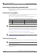
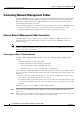
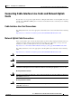
Connecting the Console Port and Auxiliary Port
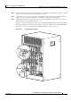
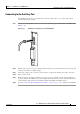
Figure 3-39 Console Port Connection on the PRE Module
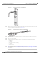
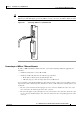
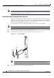
Step 2 Run the other end of the crossover cable through the square hole at the left front side of the chassis, and
connect it to the RJ-45-to-DB-9 adapter (see
Figure 3-40):
Figure 3-40 Connecting an RJ-45-to-DB-9 Console Cable Adapter
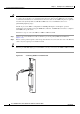
Step 3 Connect the adapter to the appropriate serial port on the PC or terminal to complete the console port
cable connection.
Step 4 Power on the PC or terminal.
Step 5 Configure the PC terminal emulation software or the terminal for the following default settings:
• 9600 baud
• 8 data bits
• No parity generation or checking
• 1 stop bit
• No flow control
Step 6 If also connecting a modem to the auxiliary port, go to the next section, “Connecting to the Auxiliary
Port.” Otherwise, go to the “Connecting Network Management Cables” section on page 3-52 to continue
the installation.
30027
CONSOLE
E
THE
RNE
T
LINK
AU
X
SLOT 0
SLO
T 1
CISCO
10000
LINK
30028