
Universal Broadband Router Hardware Installation Guide

3-49
Cisco uBR10012 Universal Broadband Router Hardware Installation Guide
OL-18259-01
Chapter 3 Installing the Cisco uBR10012 Router
Connecting the Console Port and Auxiliary Port
Connecting the Console Port and Auxiliary Port
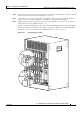
The PRE module on the Cisco uBR10012 router has two asynchronous serial (EIA/TIA-232) RJ-45 ports
that provide connections for a console (an ASCII terminal or PC running terminal emulation software)
and modem for remote access.
Recommended Tools and Supplies
The Cisco uBR10012 router arrives with a console and auxiliary cable kit, which contains the cable and
adapters you need for the most common connections to these devices.
Table 3-6 lists the tools and supplies that you need to connect the Console and auxiliary ports.
Note A crossover cable reverses pin connections from one end to the other. In other words, it connects pin 1
(at one end) to pin 8 (at the other end), pin 2 to pin 7, pin
3 to pin 6, and so on. You can identify a
crossover cable by comparing the two modular ends of the cable. Hold the cable ends in your hand,
side-by-side, with the tabs at the back. Ensure that the wire connected to the outside (left) pin of the left
plug (pin 1) is the same color as the wire connected to the outside (right) pin of the right plug (pin 8).
Also see “How to Identify an RJ-45 Crossover Cable” section on page B-5.
Use the following procedures to connect to the console and auxiliary ports on a PRE module.
Note For more information about the console port and auxiliary port connectors, see the “Console and
Auxiliary Port Cables and Pinouts” section on page B-2.
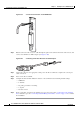
Connecting to the Console Port
The console port provides local administrative access to the router and its command-line interface (CLI).
Note Each PRE module must have a console port connection (typically to a terminal server) when running a
redundant configuration in the chassis.
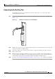
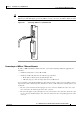
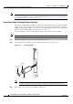
Step 1 Connect one end of the RJ-45 crossover cable to the serial RJ-45 port (labelled CONSOLE) on the PRE
module (
Figure 3-39).
Ta b l e 3-6 Tools and Supplies for Connecting the Console Port and Auxiliary Port
Quantity Description Comments
— RJ-45 to RJ-45 crossover cable —
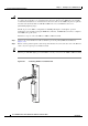
— RJ-45-to-DB-25 male DCE adapter labeled MODEM
— ESD-preventive wrist strap —