
Universal Broadband Router Hardware Installation Guide


3-42
Cisco uBR10012 Universal Broadband Router Hardware Installation Guide
OL-18259-01
Chapter 3 Installing the Cisco uBR10012 Router
Installing the Slot Splitter and Half-Height Gigabit Ethernet Line Card
Installing the Slot Splitter and Half-Height Gigabit Ethernet Line
Card
This section describes how to install the line card in the Cisco uBR10012 router. This section includes
the following tasks:
• Installing the Slot Splitter, page 3-42
• Installing the Half-Height Gigabit Ethernet Line Card, page 3-46
Caution You must use slot 3 or slot 4 when installing the slot splitter and HHGE line card in the Cisco uBR10012
router, using slot 1 or slot 2 will cause the router to shut down those slots.
Caution Do not install two half-height blank faceplates into the same slot in the slot splitter. Instead, install a
full-slot blank faceplate into the slot. The half-height blank faceplates do not have air dams, and the
empty slot will rob cooling air from the other slots. A slot splitter with one half-height line card and one
blank faceplate is allowed.
Caution Do not install a line card into the slot splitter before installing the splitter into the chassis. The slot
splitter does not have ejector levers that allow you to seat the line card in the backplane.
Installing the Slot Splitter
You must install the half-height line card into a slot that contains a slot splitter, which can hold two
half-height line cards. If both slots of the slot splitter are not used, then you must install a blank faceplate
in the empty slot.
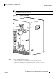
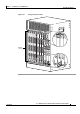
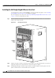
Follow these steps to install a slot splitter into slot 3 or slot 4 (Figure 3-33) of the Cisco uBR10012
chassis.
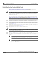
Step 1 Attach an antistatic wrist strap to your wrist and to an ESD socket on the chassis, or to a bare metal
surface on the chassis or frame.
Step 2 Grasp the front of the slot splitter with one hand and place your other hand under the splitter. Position
the splitter in front of the card cage slot.
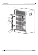
Step 3 Carefully align the upper and lower edges of the slot splitter with the upper and lower guides in the
chassis, and slide the splitter into the slot until the front is flush with the chassis.
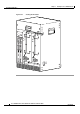
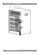
Note The slot splitter shown in Figure 3-34 has one open slot (top) and one slot with a slot cover
(bottom)
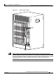
Secure the slot splitter to the chassis by tightening the top and bottom captive screws (Figure 3-35).