
Universal Broadband Router Hardware Installation Guide


3-39
Cisco uBR10012 Universal Broadband Router Hardware Installation Guide
OL-18259-01
Chapter 3 Installing the Cisco uBR10012 Router
Reinstalling the Modules
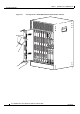
Reinstalling the Line Cards and Uplink Cards
After the chassis has been firmly attached to the rack, reinstall the cards in the chassis (also see
Removing and Replacing a Cable Interface Line Card, page 5-60 for details).
Caution The Cisco uBR10012 router supports only the Cisco uBR10-LCP2-MC28C cable interface line card or
Cisco uBR10-LCP2-MC16x cable interface line card bundles. Do not install the Cisco uBR10-LCP2
adapter card in the Cisco
uBR10012 chassis without either the Cisco MC16x or the Cisco MC28C
installed in the adapter card.
Also, do not attempt to remove the Cisco MC28C card or the Cisco MC16x card from their carriers
(adapter cards) while the they are installed in the chassis. See the
“Removing and Replacing a Cable
Interface Line Card” section on page 5-60 for information on this procedure.
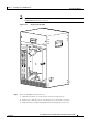
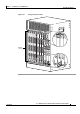
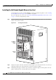
Step 1 Grasp the faceplate of the first line card with one hand and place your other hand under the card carrier
(to support the weight of the card) and position the card in front of the appropriate card cage slot.
Step 2 Carefully align the upper and lower edges of the line card with the upper and lower guides in the chassis,
and slide the cable interface line card into the slot until you can feel it begin to seat in the backplane
connectors (
Figure 3-31).
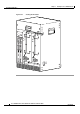
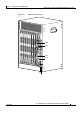
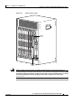
Step 3 Simultaneously pivot both ejector levers toward each other (until they are parallel to the faceplate) to
firmly seat the card in the backplane (
Figure 3-32).
Step 4 Finger tighten the captive screws to secure the card in the chassis.
Caution Do not tighten the captive screws until after you insert all the additional cards. Tightening the captive
screws before all the line cards are installed, can cause the installation slot for the last line card to be
restricted and make it difficult to install the card.
Step 5 Repeat Step 1through Step 4 for each cable interface line card and network uplink card.
Step 6 After all the line cards and network uplink cards are inserted, tighten the captive screws. (Torque 5 to
7
in-lbs.)
Tip Tighten line card 1, then tighten line card 8, tighten line card 2 then line card 7. Alternate back
and forth between the line cards until all of them are secure in the chassis.
Tip These screws prevent accidental removal and provide proper grounding for electromagnetic
interference (EMI) shielding.