
Universal Broadband Router Hardware Installation Guide


3-36
Cisco uBR10012 Universal Broadband Router Hardware Installation Guide
OL-18259-01
Chapter 3 Installing the Cisco uBR10012 Router
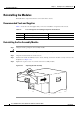
Reinstalling the Modules
Reinstalling the AC Power Entry Modules
If you are replacing DC PEMs with AC PEMS or replacing a redundant AC PEM, see Removing and
Replacing DC Power Entry Modules, page 5-8 and Removing and Replacing AC PEM Modules,
page 5-21.
Note Each of two power bays in the Cisco uBR10012 chassis is above a DC terminal block that is used
to provide power only when you are using the DC PEM modules. Do not use these DC terminal
blocks when you are using the AC PEMs. If you have previously used this Cisco
uBR10012
router with DC PEMs, first verify that these DC terminal blocks are not currently connected
before proceeding with the installation or replacement of the AC PEMs.
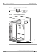
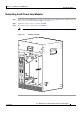
Step 1 Verify that the power switch on the replacement AC PEM is in the standby position (Figure 3-28).
Figure 3-28 AC PEM Standby Position and AC Plug Location
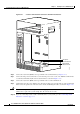
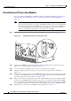
Step 2 Position the AC PEM in the power bay and push it forward, verifying that it goes all the way in and
makes a secure connection with the backplane (
Figure 3-29).
Step 3 Use the screwdriver to tighten the captive screws to secure the unit to the chassis.
Step 4 Plug the AC-input power cable into the power receptacle on the front panel of the AC PEM. See
Figure 3-28.
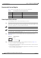
Step 5 Route the power cable up the front of the AC PEM and clip it into the two plastic retaining clips attached
to the surface of the PEM. Route the power cable out through the right side, so that it will fit through the
notch on the right side of the front bezel cover (
Figure 3-30).
Step 6 Plug the other end of the AC-input power cable into a 200–240 VAC power outlet. For fully redundant
operation, each AC PEM should use separate power sources, or you should be using an uninterruptible
power supply (UPS). The FAULT LED on the AC PEM should be yellow to indicate that the AC PEM
is receiving power from the power source but is not yet supplying power to the Cisco
uBR10012 chassis.
Step 7 Push up the power switch on the AC PEM to the ON (|) position. See Figure 3-28.
77142
ALARM
S
FAIL
PERFORMANCE ROUTING ENGINE
STATUS
ACO
CRITICAL
MINOR
MAJOR
ALARM
S
FAIL
PERFORMANCE ROUTING ENGINE
STATUS
ACO
CRITICAL
MINOR
MAJOR
AC
SWITCH
ACINPUT
200-240V
13A 50/60Hz
AC
SW
ITC
H
A
CIN
P
UT
200-24
0V
13A 50/60H
z
A
C
IN
P
U
T
200
-2
40V
13A
50
/60H
z
A
C
S
W
ITC
H