
Universal Broadband Router Hardware Installation Guide


3-33
Cisco uBR10012 Universal Broadband Router Hardware Installation Guide
OL-18259-01
Chapter 3 Installing the Cisco uBR10012 Router
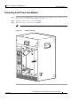
Connecting Alarm Indicators
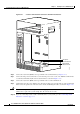
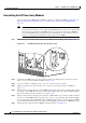
Caution Figure 3-25 shows the wiring configuration for NO alarm relays. The wiring configuration for NC alarm
relays is similar but uses the NC contacts.
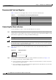
Step 4 Repeat step 3 for the remaining alarm indicators.
Step 5 Secure the power cabling to the chassis by feeding a tie wrap through the square slot on the left front
side of the chassis (next to the alarm indicator terminal block) and binding the wires.
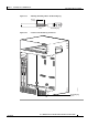
Figure 3-25 Alarm Terminal Block Connections
Step 6 Go to the next section, Connecting the Console Port and Auxiliary Port, page 3-49, to continue the
installation.
103482
A
L
A
R
M
S
C
IS
C
O
1
0
0
0
0
FA
IL
PERFORMANCE ROUTING ENGINE
C
O
N
S
O
L
E
STAT U
S
AC
O
C
RITICAL
M
IN
OR
M
AJOR
E
T
H
E
R
N
E
T
L
IN
K
A
C
T
IV
IT
Y
A
U
X
S
LO
T 0
SLO
T 1
A
L
A
R
M
S
C
IS
C
O
1
0
0
0
0
FA
IL
PERFORMANCE ROUTING ENGINE
C
O
N
S
O
L
E
STATUS
ACO
C
RITIC
AL
MIN
OR
MA
JOR
E
T
H
E
R
N
E
T
L
IN
K
A
C
T
IV
I
T
Y
A
U
X
SL
O
T 0
SLO
T 1
ALARMS
60 VDC
1A MAX
MINOR
NC NOCOM
MAJOR
NC NOCOM
CRITICAL
NC NOCOM