
Universal Broadband Router Hardware Installation Guide


3-32
Cisco uBR10012 Universal Broadband Router Hardware Installation Guide
OL-18259-01
Chapter 3 Installing the Cisco uBR10012 Router
Connecting Alarm Indicators
Recommended Tools and Supplies
Table 3-4 lists the tools and supplies that you need to connect the alarm indicators.
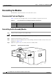
Connecting the Alarm Indicators
Use the following procedure to connect an alarm indicator to the chassis:
Step 1 Obtain sufficient wire for the desired connections. You will need two wires for each set of relays, or six
separate wires to connect all three relay contacts. Use the gauge of wire required by the audible or visual
alarm indicator equipment you are using (14 AWG maximum gauge).
Warning
Use copper conductors only.
Statement 1025
Caution The alarm contacts on the Cisco uBR10012 router are only relays and do not provide any power from
the unit. These relays are rated for 60 VDC, 1 A maximum—ensure that the connected alarm equipment
does not exceed these voltage and current ratings.
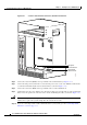
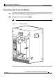
Step 2 Strip approximately 0.31 in. (8 mm) of insulation off the ends of the alarm indicator wire (see
Figure 3-24).
Figure 3-24 Stripping Insulation
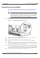
Step 3 Connect one set of alarm indicator wires to the alarm terminal block as follows (see Figure 3-25):
a. Connect one lead to the common (COM) terminal.
b. If you are wiring the router in with other equipment for the alarm indicators, wire the other lead to
the normally closed (NC) terminal.
c. If you are wiring the router in parallel with other equipment for the alarm indicators, wire the other
lead to the normally open (NO) terminal.
Ta b l e 3-4 Tools and Supplies for Connecting Alarm Indicators
Quantity Description Comments
1 Flat-blade screwdriver —
1 Wire stripping tool —
6 14 AWG wire cables —
ESD-preventive wrist strap If necessary
58688
8 mm max