
Universal Broadband Router Hardware Installation Guide


3-31
Cisco uBR10012 Universal Broadband Router Hardware Installation Guide
OL-18259-01
Chapter 3 Installing the Cisco uBR10012 Router
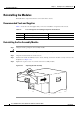
Connecting Alarm Indicators
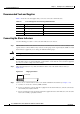
Step 11 If you are not connecting any alarm indicators, go to the “Connecting the Console Port and Auxiliary
Port” section on page 3-49 to continue the installation.
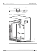
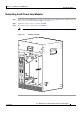
Figure 3-23 DC Power Terminal Block Connections
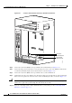
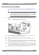
Connecting Alarm Indicators
The Cisco uBR10012 router provides relay contacts for optional (customer-supplied) audible or visual
alarm indicators. Relay contacts are provided for three levels of severity:
• Minor—This is an informational alarm and does not affect the system operation.
• Major—A condition that affects system operation and should be investigated as soon as possible.
• Critical—A condition that affects system operation and requires immediate attention.
103481
ALAR
M
S
CISCO
10000
FAIL
PERFORMANCE ROUTING ENGINE
C
O
N
S
O
L
E
STATUS
ACO
CRITICAL
MINOR
MAJOR
E
T
H
E
R
N
E
T
L
I
N
K
A
C
T
I
V
IT
Y
A
U
X
S
L
O
T
0
S
L
O
T
1
ALA
RM
S
CISCO
10000
FAIL
PERFORMANCE ROUTING ENGINE
C
O
N
S
O
L
E
STATUS
ACO
CRITICAL
MINOR
MAJOR
E
T
H
E
R
N
E
T
L
I
N
K
A
C
T
I
V
I
T
Y
A
U
X
S
L
O
T
0
S
L
O
T
1
RTN (+)
–48/–60
V