
Universal Broadband Router Hardware Installation Guide


3-30
Cisco uBR10012 Universal Broadband Router Hardware Installation Guide
OL-18259-01
Chapter 3 Installing the Cisco uBR10012 Router
Connecting DC Power to the Cisco uBR10012 Router
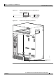
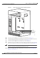
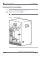
Figure 3-22 Location of the DC Power Connectors and Alarm Connections
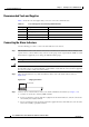
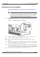
Step 6 Connect the return wire (RTN) to the top terminal in the terminal block (see Figure 3-23).
Step 7 Connect the DC power lead from the second external power source to the –48/–60VDC terminal in the
second DC
terminal block (this is the bottom terminal, as shown in Figure 3-23).
Step 8 Connect the return wire (RTN) to the top terminal in the second terminal block.
Step 9 (Optional) Secure the power cabling to the chassis by feeding a tie wrap through one of the small round
holes next to the square hole on the side of the chassis and binding the cables, as shown in
Figure 3-23.
Caution Do not connect power to the DC power sources or apply power to the Cisco uBR10012 chassis yet. This
will be done as part of the system startup after all connections are made.
Step 10 If you are connecting visual or audio alarm indicators to your system, go to the “Connecting Alarm
Indicators” section on page 3-31.
103480
ALARM
S
CIS
CO
10000
FAIL
PERFORMANCE ROUTING ENGINE
C
O
N
S
O
L
E
STATUS
ACO
CRITICAL
MINOR
MAJOR
E
T
H
E
R
N
E
T
L
I
N
K
A
C
T
I
V
I
T
Y
A
U
X
S
L
O
T
0
S
L
O
T
1
ALARM
S
CIS
CO
10000
FAIL
PERFORMANCE ROUTING ENGINE
C
O
N
S
O
L
E
STATUS
ACO
CRITICAL
MINOR
MAJOR
E
T
H
E
R
N
E
T
L
IN
K
A
C
T
IV
I
T
Y
A
U
X
S
L
O
T
0
S
L
O
T
1
DC power
terminal blocks
Visual alarm
indicator block