
Universal Broadband Router Hardware Installation Guide


3-29
Cisco uBR10012 Universal Broadband Router Hardware Installation Guide
OL-18259-01
Chapter 3 Installing the Cisco uBR10012 Router
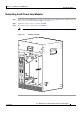
Connecting DC Power to the Cisco uBR10012 Router
Recommended Tools and Supplies
Table 3-3 lists the tools and supplies that you need to connect the Cisco uBR10012 router to DC power
sources.
Connecting the Cisco uBR10012 Chassis to a DC Power Source
Use the following procedure to connect the chassis to a DC power source:
Step 1 Double-check that the DC PEMs have been reinstalled in the system, and that no power has yet been
connected to the Cisco
uBR10012 chassis.
Step 2 Verify that the DC power source is turned off and is not supplying power to the Cisco uBR10012 chassis.
Caution If using the 2400W AC-input power shelf as the DC power source, verify that the AC-input power cords
are not plugged into AC power outlets.
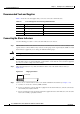
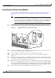
Step 3 Strip not more than 5/16 in. (8 mm) of insulation off the ends of the DC power leads (Figure 3-21).
Figure 3-21 Stripping Insulation
Warning
Use copper conductors only.
Statement 1025
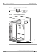
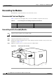
Step 4 Route the two sets of DC power leads through the square hole at the right front of the chassis. Position
each set under one of the two DC power terminal blocks (
Figure 3-22).
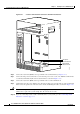
Step 5 Connect the DC power lead from the first external power source to the –48V terminal in the DC terminal
block (this is the bottom terminal, as shown in
Figure 3-23).
Ta b l e 3-3 Tools and Supplies for Connecting DC Power
Quantity Description Comments
1 Flat-blade screwdriver —
1 Wire stripping tool —
4 (length
varies)
6 AWG (16 mm
2
) wire cables Cables must reach from the Cisco uBR10012 router to
the DC power source. The end of the cable intended to
be connected to the chassis needs to have insulation
stripped back not more than 5/16-in. (8
mm).
2 Tie wraps The tie wraps bind the cables together and also bind
the cables to the side of the chassis.
Antistatic mat and ESD-wrist
strap
If necessary
58688
8 mm max