
Universal Broadband Router Hardware Installation Guide


3-28
Cisco uBR10012 Universal Broadband Router Hardware Installation Guide
OL-18259-01
Chapter 3 Installing the Cisco uBR10012 Router
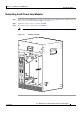
Connecting DC Power to the Cisco uBR10012 Router
Connecting DC Power to the Cisco uBR10012 Router
This section describes how to connect the Cisco uBR10012 router to the two –48/–60 VDC power
sources that provide its operating power. The DC power sources can either be already present at the site,
or they can be provided by the optional 2400W AC-input power shelf. If using the 2400W AC-input
power shelf, be certain you have already installed it, as described in the
2400W AC-Input Power Shelf
Installation Guide, available on Cisco.com at the following URL:
http://www.cisco.com/en/US/docs/cable/cmts/ubr10012/installation/field_replaceable_units/ub10acsh.
html
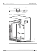
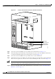
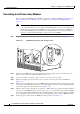
The DC power connectors are pillar terminal blocks on the backplane. For full power redundancy, each
terminal block must be connected to a separate power source. If using the optional 2400W AC-input
power shelf, full power redundancy also requires that each of the AC power supplies in the shelf be
connected to AC power sources that are on separate circuit breakers.
Warning
A readily accessible two-poled disconnect device must be incorporated in the fixed wiring.
Statement
91
Warning
Connect the unit only to DC power source that complies with the safety extra-low voltage (SELV)
requirements in IEC 60950 based safety standards.
Statement 1033
Warning
Secure all power cabling when installing this unit to avoid disturbing field-wiring connections.
Statement 38
Warning
Care must be given to connecting units to the supply circuit so that wiring is not overloaded.
Statement 51
Warning
This product requires short-circuit (overcurrent) protection, to be provided as part of the building
installation. Install only in accordance with national and local wiring regulations.
Statement 1045
Warning
Before performing any of the following procedures, ensure that power is removed from the DC circuit.
To ensure that all power is OFF, locate the circuit breaker on the panel board that services the DC
circuit, switch the circuit breaker to the OFF position, and tape the switch handle of the circuit
breaker in the OFF position.
Statement 7
Caution Be sure that you have connected the chassis to earth ground as described in the previous section before
beginning this procedure.