
Universal Broadband Router Hardware Installation Guide


3-24
Cisco uBR10012 Universal Broadband Router Hardware Installation Guide
OL-18259-01
Chapter 3 Installing the Cisco uBR10012 Router
Mounting the Chassis in the Rack
Step 1 Verify that you have removed the fan assembly module, DC PEMs, cable interface line cards, and
network uplink line cards before attempting to move the chassis (see
“Removing the Power Modules,
Fan Assembly, and Line Cards” section on page 3-4).
Caution Do not attempt to lift even a depopulated chassis by yourself. Have at least two people to lift the chassis.
Three people might be needed to position the chassis into a rack, depending on whether you are using
an equipment shelf and on how high you are mounting it.
If you have to lift the chassis to a higher location, have a third person present who can lift the middle of
the chassis as the other two people lift it straight up.
Step 2 With each person standing on a side of the chassis, bend straight down at the knees, and grab one of the
handles on the side of the chassis.
Step 3 Carefully lift the chassis straight up and walk with slow, deliberate steps to your destination.
Caution To prevent injury, keep your back straight and lift with your legs, not your back.
Step 4 When you reach your destination, bend at the knees to lower the chassis to the ground.
Step 5 Lift the chassis up to the height that it will be positioned in the rack.
Step 6 Maneuver the chassis into position in the rack.
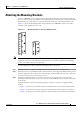
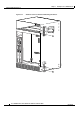
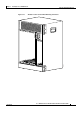
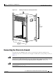
Step 7 Align the mounting bracket holes with the rack post holes (Figure 3-18) and attach the chassis to the rack
with the appropriate-sized screws (performed by the third person unless the chassis is resting on a shelf).
Step 8 Go to the Connecting the Chassis to Ground section to continue the installation.
Warning
This equipment must be grounded. Never defeat the ground conductor or operate the equipment in the
absence of a suitably installed ground conductor. Contact the appropriate electrical inspection
authority or an electrician if you are uncertain that suitable grounding is available.
Statement 1024
Note Figure 3-18 shows the chassis flush-mounted at the rear. The procedure is identical for the other
mounting methods. This figure also shows two sets of mounting brackets being used, one set at the front
and one set at the rear of the chassis. Only one set of brackets is necessary to support the chassis.