Cisco UCS C220 M3 High-Density Rack Server (Small Form Factor Disk Drive Model) CISCO SYSTEMS 170 WEST TASMAN DR SAN JOSE, CA, 95134 WWW.CISCO.COM PUBLICATION HISTORY REV A.
CONTENTS OVERVIEW . . . . . . . . . . . . . . . . . . . . . . . . . . . . . . . . . . . . . . . . . . . . . . . 3 DETAILED VIEWS . . . . . . . . . . . . . . . . . . . . . . . . . . . . . . . . . . . . . . . . . . . 4 Chassis Front View . . . . . . . . . . . . . . . . . . . . . . . . . . . . . . . . . . . . . . . . . . . . . . . . . . .4 Chassis Rear View . . . . . . . . . . . . . . . . . . . . . . . . . . . . . . . . . . . . . . . . . . . . . . . . . . .5 BASE SERVER STANDARD CAPABILITIES and FEATURES . .
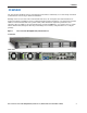
OVERVIEW OVERVIEW The Cisco® UCS C220 M3 rack server is designed for performance and density over a wide range of business workloads from web serving to distributed database. Building on the success of the Cisco UCS C200 M2 rack server, the enterprise-class UCS C220 M3 server further extends the capabilities of Cisco’s Unified Computing System portfolio in a 1U form factor with the addition of the Intel® E5-2600 series product family CPUs that deliver significant performance and efficiency gains.
DETAILED VIEWS DETAILED VIEWS Chassis Front View Figure 2 shows the Cisco UCS C220 M3 High-Density SFF Rack Server.
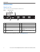
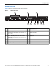
DETAILED VIEWS Chassis Rear View Figure 3 shows the external features of the rear panel.
BASE SERVER STANDARD CAPABILITIES and FEATURES BASE SERVER STANDARD CAPABILITIES and FEATURES Table 1 lists the capabilities and features of the base server. Details about how to configure the server for a particular feature or capability (for example, number of processors, disk drives, or amount of memory) are provided in CONFIGURING the SERVER, page 9.
BASE SERVER STANDARD CAPABILITIES and FEATURES Capability/Feature Storage controller Description ■ Embedded RAID (3 Gbs) • Embedded SATA-only RAID controller, supporting up to 4 SATA-only drives (RAID 0, 1, 10) • ROM5 embedded RAID upgrade, supporting up to 8 SAS/SATA drives (RAID 0, 1, 10). SAS and SATA drives can be mixed. • ROM55 embedded RAID upgrade, supporting up to 8 SAS/SATA drives (RAID 0, 1, 10, 5). SAS and SATA drives can be mixed.
BASE SERVER STANDARD CAPABILITIES and FEATURES Capability/Feature Description Fans Chassis: ■ Five hot-swappable fans for front-to-rear cooling Power supply: ■ Integrated management processor 8 Each power supply is equipped with a fan. Cisco Integrated Management Controller (CIMC) firmware. Depending on your CIMC settings, the CIMC can be accessed through the 1-Gb Ethernet dedicated management port, the 1-Gb Ethernet LOM ports, or a Cisco P81E or Cisco 1225 virtual interface card (VIC).
CONFIGURING the SERVER CONFIGURING the SERVER Follow these steps to configure the Cisco UCS C220 M3 High-Density SFF Rack Server: ■ STEP 1 VERIFY SERVER SKU, page 10 ■ STEP 2 SELECT CPU(s), page 11 ■ STEP 3 SELECT MEMORY, page 13 ■ STEP 4 SELECT RAID CONFIGURATION, page 18 ■ STEP 5 SELECT HARD DISK DRIVES (HDDs) or SOLID STATE DRIVES (SSDs), page 22 ■ STEP 6 SELECT PCIe OPTION CARD(s), page 24 ■ STEP 7 ORDER OPTIONAL NETWORK CARD ACCESSORIES, page 26 ■ STEP 8 ORDER POWER SUPPLY, page 29 ■
CONFIGURING the SERVER STEP 1 VERIFY SERVER SKU Verify the product ID (PID) of the server as shown in Table 2. Table 2 PID of the C220 M3 High-Density SFF Rack Base Server Product ID (PID) UCSC-C220-M3S Description UCS C220 M3 SFF, no CPU, memory, HDD, SDD, power supply, SD card, or PCIe cards, with 1 rail kit The Cisco C220 M3 server: ■ Includes one tool-less rail kit ■ Does not include power supply, CPU, memory, hard disk drives (HDDs), solid-state drives (SSDs), SD card, or plug-in PCIe cards.
CONFIGURING the SERVER STEP 2 SELECT CPU(s) The standard CPU features are: ■ Intel E5-2600 series processor family CPUs ■ Intel C600 series chipset ■ Cache size of 10, 15, or 20 MB Select CPUs The available CPUs are listed in Table 3. Table 3 Available Intel CPUs: E5-2600 Series Processor Family CPUs Product ID (PID) Intel Number Clock Freq (GHz) Power (W) Cache Size (MB) Cores QPI Highest DDR3 DIMM Clock Support (MHz)1 UCS-CPU-E5-2690 E5-2690 2.
CONFIGURING the SERVER Approved Configurations (1) 1-CPU configurations: ■ Select any one CPU listed in Table 3. (2) 2-CPU Configurations: ■ Select two identical CPUs from any one of the rows of Table 3 on page 11. Caveats 12 ■ You can select either one processor or two identical processors. ■ For optimal performance, select DIMMs with the highest clock speed for a given processor (see Table 3 on page 11).
CONFIGURING the SERVER STEP 3 SELECT MEMORY The standard memory features are: ■ ■ Figure 4 DIMMs — Clock speed: 1333 or 1600 MHz — Ranks per DIMM: 1, 2, or 4 — Operational voltage: dual voltage capable (1.5 V or 1.35 V) — Registered ECC DDR3 DIMMS (RDIMMS) or load-reduced DIMMS (LRDIMMs) Memory is organized with four memory channels per CPU, with up to two DIMMs per channel, as shown in Figure 4.
CONFIGURING the SERVER Select DIMMs and Memory Mirroring Select the memory configuration and whether or not you want the memory mirroring option. The available memory DIMMs and mirroring option are listed in Table 4. NOTE: When memory mirroring is enabled, the memory subsystem simultaneously writes identical data to two channels. If a memory read from one of the channels returns incorrect data due to an uncorrectable memory error, the system automatically retrieves the data from the other channel.
CONFIGURING the SERVER Approved Configurations (1) 1-CPU configuration without memory mirroring: ■ Select from 1 to 8 DIMMs. Refer to Memory Population Rules, page 50, for more detailed information. (2) 1-CPU configuration with memory mirroring: ■ Select 2, 4, 6, or 8 identical DIMMs. The DIMMs will be placed by the factory as shown in the following table.
CONFIGURING the SERVER (4) 2-CPU configuration with memory mirroring: ■ Select 2, 4, 6, or 8 identical DIMMs per CPU. The DIMMs will be placed by the factory as shown in the following table.
CONFIGURING the SERVER Caveats ■ The server supports registered DIMMs (RDIMMs) or load-reduced DIMMS (LRDIMMs), however, do not mix RDIMMs and LRDIMMs in a server. ■ When using mirroring, DIMMs must be installed in identical pairs across paired DDR3 buses. That is, mirrored pairs in channels A and B must be identical and pairs in channels C and D must be identical. However, the DIMMs used in channels A and B and in C and D can be different. ■ UDIMMs and non-ECC DIMMs are not supported.
CONFIGURING the SERVER STEP 4 SELECT RAID CONFIGURATION The RAID controller choices are: ■ Embedded RAID (on motherboard) NOTE: If you do not select a mezzanine card, a plug-in PCIe RAID card, or one of the embedded RAID upgrade options, you will have an embedded SATA-only RAID controller that supports up to four SATA-only drives (RAID 0, 1, 10) ■ Mezzanine RAID controller cards ■ Plug-in PCIe RAID controller cards Cisco can provide factory-configured RAID systems depending on the RAID controller c
CONFIGURING the SERVER Table 6 Available Mezzanine Card RAID Options Product ID (PID) PID Description RAID Controllers UCSC-RAID-11-C220 Cisco UCSC RAID SAS 2008M-8i Mezzanine Card (RAID 0, 1, 10, 5, and 50 supported), operating at 6 Gbs. ■ Supports up to eight internal SAS or SATA drives. SAS and SATA drives can be mixed.
CONFIGURING the SERVER Table 7 Available Plug-In PCIe Card RAID Options (continued) Product ID (PID) PID Description RAID Configuration Options R2XX-RAID0 Factory preconfigured RAID striping option Enable RAID 0 Setting. Requires a minimum of one hard drive. R2XX-RAID1 Factory preconfigured RAID mirroring option Enable RAID 1 Setting. Requires exactly two drives with the same size, speed, capacity. R2XX-RAID5 Factory preconfigured RAID option Enable RAID 5 Setting.
CONFIGURING the SERVER Approved Configurations (1) 1-CPU Configurations Mezzanine cards are not supported for 1-CPU configurations, Therefore, only the following RAID controllers are supported for single-CPU configurations: ■ Embedded RAID ■ LSI MegaRAID SAS 9266-8i ■ LSI MegaRAID SAS 9266CV-8i (2) 2-CPU Configurations Select an embedded RAID option from Table 5, one mezzanine RAID controller from Table 6 on page 19, or one PCIe RAID controller from Table 7 on page 19.
CONFIGURING the SERVER STEP 5 (SSDs) SELECT HARD DISK DRIVES (HDDs) or SOLID STATE DRIVES The standard disk drive features are: ■ 2.5-inch small form factor ■ Hot-pluggable ■ Sled-mounted Select Drives The available drives are listed in Table 8. Table 8 Available Hot-Pluggable Sled-Mounted HDDs and SSDs PID Description Drive Type Capacity A03-D1TBSATA 1TB SATA 7.
CONFIGURING the SERVER Approved Configurations (1) Onboard RAID, Mezzanine Cards, and all Plug-In RAID Controllers ■ If you have not selected an onboard RAID upgrade option (ROM5 or ROM55), a mezzanine card, or a plug-in RAID controller, you may select up to 4 SATA-only drives. ■ Otherwise, select up to eight SAS/SATA drives listed in Table 8. You can mix SAS and SATA drives. Caveats ■ You can mix SATA and SAS drives.
CONFIGURING the SERVER STEP 6 SELECT PCIe OPTION CARD(s) The standard PCie card offerings are: ■ Converged Network Adapters (CNAs) ■ Network Interface Cards (NICs) ■ Host Bus Adapters (HBAs) Select PCIe Option Cards The available PCIe option cards are listed in Table 9.
CONFIGURING the SERVER Approved Configurations (1) No RAID controller plug-in card ■ If you did not choose a plug-in RAID controller (for example, you are using embedded RAID or a mezzanine RAID controller), you can select up to two PCie option cards listed in Table 9. (2) One RAID controller plug-in card ■ If you selected a plug-in PCIe RAID controller, you can select only one of the optional PCIe cards listed in Table 9.
CONFIGURING the SERVER STEP 7 ORDER OPTIONAL NETWORK CARD ACCESSORIES Copper twinax cables and SFP optical modules may be ordered to support the two-port network cards that are available with the server. Choose Optional Twinax Cables Table 10 lists the copper twinax cables available for the PCIe cards. You can choose cable lengths of 1, 3, 5, 7, or 10 meters.
CONFIGURING the SERVER Choose Optional SFP Modules Optical Cisco SFP+ modules are listed in Table 11. Table 11 Available SFP Modules Product ID (PID) PID Description SFP-10G-SR 10GBASE-SR SFP+ Module 850 nm, multimode, SR, 3.3V, LC connector, with Digital Optical Monitoring DS-SFP-FC8G-SW 8 Gbit SFP+ Module 850 nm, multimode, SR, 3.
CONFIGURING the SERVER Figure 5 28 Network Card Connections Cisco UCS Cisco UCS C220 M3 High-Density Rack Server (Small Form Factor Disk Drive Model)
CONFIGURING the SERVER STEP 8 ORDER POWER SUPPLY The C220 M3 SFF server accommodates two power supplies. A lightly loaded server can operate from one 650 W power supply. A fully loaded server might need to be powered with two 450 W or two 650 W power supplies (see Table 12). Use the power calculator at the following link to determine the needed power based on the options chosen (CPUs, drives, memory, and so on): https://express.salire.com/Go/Cisco/Cisco-UCS-Power-Calculator.
CONFIGURING the SERVER STEP 9 SELECT AC POWER CORD(s) Using Table 13, select the appropriate AC power cords. You can select a minimum of no power cords and a maximum of two. If you select the option R2XX-DMYMPWRCORD, no power cord is shipped with the server.
CONFIGURING the SERVER Table 13 Available Power Cords Product ID (PID) PID Description SFS-250V-10A-AR Power Cord, SFS, 250V, 10A, Argentina Images 2500 mm Cordset rating: 10 A, 250/500 V MAX Length: 8.
CONFIGURING the SERVER Table 13 Available Power Cords Product ID (PID) PID Description CAB-9K10A-IT Power Cord, 250VAC 10A CEI 23-16/VII Plug, Italy Images Cordset rating: 10 A, 250 V Length: 8 ft 2 in. (2.5 m) Connector C15M (EN60320/C15 ) 186575 Plug: I/3G (CEI 23-16) CAB-9K10A-SW Power Cord, 250VAC 10A MP232 Plug, Switzerland Cordset rating: 10 A, 250 V Length: 8 ft. 2 in (2.
CONFIGURING the SERVER STEP 10 ORDER OPTIONAL REVERSIBLE CABLE MANAGEMENT ARM The reversible cable management arm mounts on either the right or left slide rails at the rear of the server and is used for cable management. Use Table 14 to order a cable management arm.
CONFIGURING the SERVER STEP 11 ORDER A TRUSTED PLATFORM MODULE Trusted Platform Module (TPM) is a computer chip (microcontroller) that can securely store artifacts used to authenticate the platform (server). These artifacts can include passwords, certificates, or encryption keys. A TPM can also be used to store platform measurements that help ensure that the platform remains trustworthy.
CONFIGURING the SERVER STEP 12 ORDER CISCO FLEXIBLE FLASH SD CARD MODULE (OPTIONAL) You can order one optional 16 GB Cisco Flexible Flash secure digital (SD) card. This SD card contains preloaded software for simplified server operation. The ordering information is listed in Table 16. Table 16 Secure Digital (SD) Card Product ID (PID) PID Description UCSC-SD-16G-C220 16GB SD Card for C220 servers See Figure 6 on page 47 for the location of the SD cards.
CONFIGURING the SERVER STEP 13 ORDER OPTIONAL USB 2.0 DRIVE You may order one optional USB 2.0 drive. The USB drive ordering information is listed in Table 17. Table 17 USB 2.0 Drive Product ID (PID) PID Description UCS-USBFLSH-S-4GB 4GB Flash USB Drive (shorter length) for all servers except C260 See Figure 6 on page 47 for the location of the USB connector.
CONFIGURING the SERVER STEP 14 SELECT OPERATING SYSTEM Several operating systems are available from which to choose. Select one of the operating systems shown in Table 18.
CONFIGURING the SERVER Table 18 38 Operating Systems (continued) PID Description Product ID (PID) VMW-VS5-STD-3A VMware vSphere 5 Standard for 1 Processor, 3 Year, Support Required VMW-VS5-STD-4A VMware vSphere 5 Standard for 1 Processor, 4 Year, Support Required VMW-VS5-STD-5A VMware vSphere 5 Standard for 1 Processor, 5 Year, Support Required VMW-VS5-ENT-1A VMware vSphere 5 Enterprise for 1 Processor, 1 Year Support Required VMW-VS5-ENT-2A VMware vSphere 5 Enterprise for 1 CPU, 2 Yr Support
CONFIGURING the SERVER STEP 15 SELECT OPERATING SYSTEM MEDIA KIT Select the optional operating system media listed in Table 19.
CONFIGURING the SERVER STEP 16 SELECT OPTIONAL VALUE-ADDED SOFTWARE You can select from a variety of value-added software listed in Table 20.
CONFIGURING the SERVER STEP 17 SELECT SERVICE and SUPPORT LEVEL A variety of service options are available, as described in this section. Unified Computing Warranty, No Contract If you have noncritical implementations and choose no service contract, the following coverage is supplied: ■ Three-year parts coverage. ■ Next business day (NBD) parts replacement eight hours a day, five days a week. ■ 90-day software warranty on media. ■ Downloads of BIOS, drivers, and firmware updates.
CONFIGURING the SERVER Unified Computing Warranty Plus Service For faster parts replacement than is provided with the standard Cisco Unified Computing System warranty, Cisco offers the Cisco Unified Computing Warranty Plus Service. You can choose from several levels of advanced parts replacement coverage, including onsite parts replacement in as little as two hours.
CONFIGURING the SERVER Table 23 Drive Retention Service Options Service Description UCS Mission Critical Support Service With Drive Retention UCS Support Service With Drive Retention UCS Warranty Plus With Drive Retention Service Program Name Service Level GSP Service Level Product ID (PID) UC CRIT DR UCMD7 24x7x4 Onsite CON-UCMD7-C220-M3-WSFF UCMD8 24x7x2 Onsite CON-UCMD8-C220-M3-WSFF UCSD1 8x5xNBD CON-UCSD1-C220-M3-WSFF UCSD2 8x5x4 CON-UCSD2-C220-M3-WSFF UCSD3 24x7x4 CON-UCSD3-C220-
CONFIGURING the SERVER Mission Critical Support Service is a layered service available for all Cisco data center products already support by a UCS Support Service or SMARTnet service contract. For further information about Cisco Mission Critical Support Service, please consult the Service Description that can be found at the following link: http://www.cisco.com/web/about/doing_business/legal/service_descriptions/index.html or contact your Cisco account Manager.
OPTIONAL STEP - ORDER RACK(s) OPTIONAL STEP - ORDER RACK(s) The optional R42610 rack is available from Cisco for the C-Series servers, including the C220 M3 SFF server. This rack is a standard 19-inch rack and can be ordered with a variety of options, as listed in Table 24. Racks are shipped separately from the C220 M3 SFF server.
OPTIONAL STEP - ORDER PDU OPTIONAL STEP - ORDER PDU An optional power distribution unit (PDU) is available from Cisco for the C-Series rack servers, including theC220 M3 server. This PDU is available in a zero rack unit (RU) style (see Table 24). Table 25 PDU Options Product ID (PID) PID Description RP208-30-2P-U-2 Zero RU PDU For more information about the PDU, see PDUs, page 57.
SUPPLEMENTAL MATERIAL SUPPLEMENTAL MATERIAL CHASSIS An internal view of the C220 M3 chassis with the top cover removed is shown in Figure 6.
SUPPLEMENTAL MATERIAL 7 CPUs and heatsinks (two) 16 Power supplies (two, hot-swappable access through rear panel) 8 Integrated RAID on motherboard, and mini-SAS connectors 17 RTC battery on motherboard 9 Mezzanine RAID card, mini-SAS connectors SAS1 and SAS2 18 Software RAID 5 header (RAID key). CPUs and DIMMs Physical Layout Each CPU has four DIMM channels: ■ CPU1 has channels A, B, C, and D ■ CPU2 has channels E, F, G, and H Each DIMM channel has two banks: bank 1 and bank 2.
SUPPLEMENTAL MATERIAL Figure 7 Physical Layout of CPU DIMM Channels and Banks C1 C2 D1 D2 CPU1 Front of Server B2 B1 A2 A1 G1 G2 H1 H2 F2 F1 E2 E1 331707 CPU2 Cisco UCS Cisco UCS C220 M3 High-Density Rack Server (Small Form Factor Disk Drive Model) 49
SUPPLEMENTAL MATERIAL Memory Population Rules When considering the memory configuration of your server, you should consider the following items: ■ For optimum performance, populate at least one DIMM per memory channel per CPU. If using 4 GB DIMMs, you must populate 2 DIMMs per CPU memory channel. ■ The server supports registered DIMMs (RDIMMs) or load-reduced DIMMS (LRDIMMs), however, do not mix RDIMMs and LRDIMMs in a server.
SUPPLEMENTAL MATERIAL Recommended Memory Configuration This section explains the recommended DIMM population order rules for the C220 M3 server. ■ All DIMMs must be DDR3 DIMMs. ■ Do not mix: — DIMMs with different sizes or clock rates in a bank — RDIMMs and LRDIMMs — ECC and non-ECC DIMMs ■ There are blue and black DIMM slots. Populate blue slots first.
SUPPLEMENTAL MATERIAL Table 27 Recommended Memory Configurations (continued) Total System Memory Size 192 GB 256 GB 512 GB CPU 1 DIMMs CPU 2 DIMMs DIMM Max Operating Speed (MHz) Total DIMMs in the System1 2x16 GB 1600 12 4x16 GB 4x8 GB 1600 16 1x32 GB 2x32 GB 1x32 GB 1600 6 4x16 GB 4x16 GB 4x16 GB 4x16 GB 1600 16 2x32 GB 2x32 GB 2x32 GB 2x32 GB 1600 8 4x32 GB 4x32 GB 4x32 GB 4x32 GB 1600 16 Blue Slots Bank 1 (A1, B1, C1, D1) Black Slots Bank 2 (A2, B2, C2, D2) Blue Sl
SUPPLEMENTAL MATERIAL Supported DIMM Populations The supported DIMM populations are listed in Table 28.
SUPPLEMENTAL MATERIAL Low-Voltage DIMM Considerations The C220 M3 server can be ordered with dual-voltage (1.5/1.35 V) DIMMs only. Note the following considerations: ■ Low-voltage DIMMs within the server must have the identical manufacturer, type, speed, and size. ■ Low-voltage DIMMs and standard-voltage DIMMs can be mixed in the same server. Note that this causes the system BIOS to default to standard-voltage operation (Performance Mode).
SUPPLEMENTAL MATERIAL RACKS The Cisco R42610 rack (see Figure 8) is certified for Cisco UCS installation at customer sites and is suitable for the following equipment: ■ Cisco UCS B-Series servers and fabric interconnects ■ Cisco UCS C-Series and select Nexus switches The rack is compatible with hardware designed for EIA-standard 19-inch racks. Rack specifications are listed in Table 29. Table 29 Cisco R42610 Rack Specifications Parameter Standard Rack Expansion Rack Dimensions (H x W x D) 78.
SUPPLEMENTAL MATERIAL Figure 8 Cisco R42610 Rack Front view - door closed 56 Front view - door open Front view - door removed Cisco UCS Cisco UCS C220 M3 High-Density Rack Server (Small Form Factor Disk Drive Model)
SUPPLEMENTAL MATERIAL PDUs Cisco RP Series Power Distribution Units (PDUs) offer power distribution with branch circuit protection. Cisco RP Series PDU models distribute power to up to 24 outlets. The architecture organizes power distribution, simplifies cable management, and enables you to move, add, and change rack equipment without an electrician. With a Cisco RP Series PDU in the rack, you can replace up to two dozen input power cords with just one.
SUPPLEMENTAL MATERIAL KVM CABLE The KVM cable provides a connection into the server, providing a DB9 serial connector, a VGA connector for a monitor, and dual USB ports for a keyboard and mouse. With this cable, you can create a direct connection to the operating system and the BIOS running on the server. The KVM cable ordering information is listed in Table 30.
SUPPLEMENTAL MATERIAL Motherboard USB and SD Ports, and RAID Card Backup Location The C220 M3 SFF motherboard has a general-purpose USB socket, and two SD sockets as shown in Figure 11. The mounting location for the RAID SuperCap data cache power backup module is also shown.
TECHNICAL SPECIFICATIONS TECHNICAL SPECIFICATIONS Dimensions and Weight Table 31 UCS C220 M3 Dimensions and Weight Parameter Value Height 1.7 in. (4.32 cm) Width 16.92 in.(43.0 cm) Depth 28.5 in. (72.4cm) Front Clearance 3 in. (76 mm) Side Clearance 1 in. (25 mm) Rear Clearance 6 in. (152 mm) Weight Maximum (8 HDDs, 2 CPUs, 16 DIMMs, 2 power supplies) 35.6 lbs (16.2 kg) Minimum (1 HDD, 1 CPU, 1 DIMM, 1 power supply) 26.8 lbs (12.
TECHNICAL SPECIFICATIONS Table 32 UCS C220 M3 SFF 450 W Power Supply Specifications Description Specification Power supply efficiency CSCI Platinum NOTE: AC input connector is an IEC 320 C-14 15A/250VAC power inlet. The general power specifications for the C220 M3 SFF server 650 W power supply are listed in Table 32.
TECHNICAL SPECIFICATIONS Environmental Specifications The power specifications for the C220 M3 server are listed in Table 34. Table 34 UCS C220 M3 Environmental Specifications Parameter Minimum Temperature operating 41 to 104° F (5 to 40° C) derate the maximum temperature by 1°C per every 305m of altitude above sea level Temperature nonoperating –40 to 149°F (–40 to 65°C) Humidity (RH) nonoperating, non-condensing 10 to 90% Altitude operating 0 to 3,000 m (0 to 10,000 ft.
TECHNICAL SPECIFICATIONS Compliance Requirements The regulatory compliance requirements for C-Series servers are listed in Table 35. Table 35 UCS C-Series Regulatory Compliance Requirements Parameter Description Regulatory Compliance Products should comply with CE Markings per directives 2004/108/EC and 2006/95/EC Safety UL 60950-1 Second Edition CAN/CSA-C22.2 No.
TECHNICAL SPECIFICATIONS 64 Cisco UCS Cisco UCS C220 M3 High-Density Rack Server (Small Form Factor Disk Drive Model)