
Network Router User Manual

B-16
Cisco uBR924 Software Configuration Guide
OL-0337-05 (8/2002)
Appendix B Using the Cable Monitor Tool
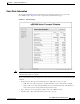
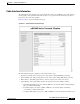
Sample Pages
–
ranging_2_state—Ranging 2 state
–
dhcp_state—DHCP state
–
establish_tod_state—Time of Day state
–
security_association_state—Security Association state
–
configuration_file_state—Download Configuration File state
–
registration_state—Registration state
–
establish_privacy_state—Establish Privacy state
–
maintenance_state—Maintenance state
• Ranging SID—The SID assigned to the router by the CMTS.
• Registered—Indicates whether the router successfully registered with the CMTS.
• Privacy Established—Indicates whether the router established a BPI security session with the
CMTS.
• TFTP Server IP Address—Shows the IP address for the TFTP server that downloaded the DOCSIS
configuration file to the router.
• Time Server IP Address—Shows the IP address for the ToD server that provided the correct
time-of-day to the router.
• Time Zone Offset—Shows the time zone that the router has been configured to use.
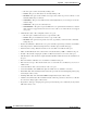
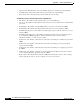
• Downstream Info—Click this link to display the following downstream characteristics:
–
DS ID—The Downstream ID assigned to the router.
–
DS Frequency—The frequency in MHz of the downstream assigned to the router.
–
DS Symbol Rate—The symbol rate currently used on the downstream.
–
DS QAM Mode—The bandwidth used on the downstream (64 QAM or 25 6QAM).
–
Signal-to-Noise Ratio Estimate—The current SNR calculated for the downstream.
–
DS Lock Threshold—The minimum SNR signal that the router requires to maintain a lock on
the downstream signal.
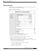
• Upstream Info—Click this link to display the following upstream characteristics:
–
US ID—The Upstream ID assigned to the router.
–
US Frequency—The frequency in MHz of the upstream assigned to the router.
–
US Power Level—The target power level that the router should be using on the upstream.
–
US Symbol Rate—The symbol rate currently used on the upstream.
–
Ranging Offset—The delay correction, in units of 6.25 microseconds, that the router must apply
to the CMTS Upstream Frame Time to synchronize upstream transmissions.
–
Mini-Slot Size—The size of the DOCSIS mini-slots in units of 6.25 microseconds. Possible
values are 2, 4, 8, 16, 32, 64, or 128.
–
Change Count—The DOCSIS configuration change count, which tracks how many times the
UCD parameters for a router have changed.
• Configuration File Info—Click this link to display the contents of the DOCSIS configuration file
that the router downloaded during its power-on provisioning.