Cisco uBR924 Cable Access Router Software Configuration Guide 12.2(8) August 2002 Corporate Headquarters Cisco Systems, Inc. 170 West Tasman Drive San Jose, CA 95134-1706 USA http://www.cisco.
THE SPECIFICATIONS AND INFORMATION REGARDING THE PRODUCTS IN THIS MANUAL ARE SUBJECT TO CHANGE WITHOUT NOTICE. ALL STATEMENTS, INFORMATION, AND RECOMMENDATIONS IN THIS MANUAL ARE BELIEVED TO BE ACCURATE BUT ARE PRESENTED WITHOUT WARRANTY OF ANY KIND, EXPRESS OR IMPLIED. USERS MUST TAKE FULL RESPONSIBILITY FOR THEIR APPLICATION OF ANY PRODUCTS.
C O N T E N T S Preface vii Audience Purpose vii viii Organization viii Document Conventions Acronyms and Terms viii xi Related Documentation xii Cisco uBR924 Cable Access Router xii CMTS Hardware Installation Publications xiii Cisco IOS Publications xiii Configuration Editor and Network Management Publications Subscriber Publications xiii xiii Obtaining Documentation xiv World Wide Web xiv Documentation CD-ROM xiv Ordering Documentation xiv Obtaining Technical Assistance xiv Cisco Connection Onli
Contents DOCSIS Baseline Privacy Interface 1-6 Dynamic Host Configuration Protocol Server 1-6 Dynamic Host Configuration Protocol Proxy Support 1-7 Enhanced IP Bridging 1-7 Ecosystem Gatekeeper Interoperability Enhancements 1-7 Fax over IP 1-8 H.323v2 (Gateway/Gatekeeper) 1-8 IP Address Negotiation 1-9 IPsec Network Security 1-9 Layer 2 Tunneling Protocol 1-9 Media Gateway Control Protocol V12.1.
Contents Reconfiguring DOCSIS-Compliant Bridging CHAPTER 3 Advanced Data-Only Configurations Data-Only Routing 2-9 3-1 3-2 Routing with DHCP Server NAT/PAT Configuration 3-4 3-6 NAT/PAT Configuration with DHCP Proxy 3-8 Using NAT and DHCP Proxy and Copying Configuration Files 3-10 IPSec (56-bit) Example 3-11 Sample Configuration 3-13 Additional Documentation 3-15 IPSec (3DES) Example L2TP Example CHAPTER 4 3-16 3-17 Voice over IP Configurations 4-1 Overview 4-1 Introduction 4-2 Voice Hand
Contents Command History Features A-7 Displaying the Command History A-7 Editing Previous Commands A-7 Command History Buffer Size A-8 Using Output Modifiers A-8 Understanding Cisco IOS Configuration Files A-9 Downloading the Configuration File A-9 Startup and Run-Time Configuration Files A-10 Displaying the Configuration Files A-10 File Format A-11 Useful Commands APPENDIX A-11 Using the Cable Monitor Tool B B-1 Enabling the Cable Monitor B-2 Configuration Modes B-2 Security Considerations B-3 Disab
Preface This document is the Cisco uBR924 Cable Access Router Software Configuration Guide and describes the configuration of the Cisco uBR924 cable access router.
Preface Purpose Purpose This configuration guide explains the initial and basic software configuration procedures for the Cisco uBR924 cable access router. This guide contains procedures for configuring the Cisco uBR924 router for both data only operation, as well as for voice and data operation. This guide also describes how to set up basic security, the headend interface (CMTS-to-CM), and how to use ROM monitor.
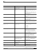
Preface Document Conventions Convention Meaning Comments Boldface Commands and keywords you enter offset-list literally as shown Italics Variables for which you supply values command type interface You replace the variable with the type of interface. In contexts that do not allow italics, such as online help, arguments are enclosed in angle brackets (< >). Square brackets ([ ]) Optional elements command [abc] abc is optional (not required), but you can choose it.
Preface Document Conventions Caution Note Timesaver Means reader be careful. You are capable of doing something that might result in equipment damage or loss of data. Means reader take note. Notes contain helpful suggestions or references to materials not contained in this guide. Means the described action saves time. You can save time by performing the action described in the paragraph. Warning This warning symbol means danger. You are in a situation that could cause bodily injury.
Preface Acronyms and Terms Avvertenza Questo simbolo di avvertenza indica un pericolo. Si è in una situazione che può causare infortuni. Prima di lavorare su qualsiasi apparecchiatura, occorre conoscere i pericoli relativi ai circuiti elettrici ed essere al corrente delle pratiche standard per la prevenzione di incidenti.
Preface Related Documentation • DES—Data Encryption Standard. • DOCSIS 1.0—Data Over Cable Service Interface Specification. • DOCSIS 1.0+—Extension of the DOCSIS 1.0 standard with features that support quality of service (QoS) options to offer better than best effort, low latency, and low jitter services. • Downstream—Transmission of traffic from the CMTS (headend) to the CM (cable modem). • IPSec—IP network security. • Kbps—Kilobits per second. • MAC—Media Access Control.
Preface Related Documentation Note The Cisco uBR924 Cable Access Router Installation and Configuration Guide is still available on CCO but has been superseded by the hardware and software guides listed above.
Preface Obtaining Documentation Note Service provider and subscriber publications for other models of Cisco uBR900 Series cable access routers are also available on CCO. Obtaining Documentation World Wide Web You can access the most current Cisco documentation on the World Wide Web at http://www.cisco.com, http://www-china.cisco.com, or http://www-europe.cisco.com. Documentation CD-ROM Cisco documentation and additional literature are available in a CD-ROM package, which ships with your product.
Preface Obtaining Technical Assistance CCO’s broad range of features and services helps customers and partners to streamline business processes and improve productivity. Through CCO, you will find information about Cisco and our networking solutions, services, and programs. In addition, you can resolve technical issues with online support services, download and test software packages, and order Cisco learning materials and merchandise.
Preface Obtaining Technical Assistance You can e-mail your comments to bug-doc@cisco.com. To submit your comments by mail, for your convenience many documents contain a response card behind the front cover. Otherwise, you can mail your comments to the following address: Cisco Systems, Inc. Document Resource Connection 170 West Tasman Drive San Jose, CA 95134-9883 We appreciate and value your comments.
C H A P T E R 1 Overview This chapter provides a basic understanding of the Cisco uBR924 cable access router’s software feature sets, as well as the processes used for provisioning the router within a cable network and configuring it for different services.
Chapter 1 Overview Cisco IOS Software Release Feature Sets Note • Base IP DOCSIS-Compliant Bridging—Provides full DOCSIS 1.0-compliant cable modem support for customers who want a basic high-speed connection to the Internet. This is the default software image for the Cisco uBR924 cable access router in Cisco IOS Release 12.0; in Cisco IOS Release 12.1 and later, this image is superseded by the Home Office (Easy IP) image.
Chapter 1 Overview Cisco IOS Software Release Feature Sets DOCSIS-compliant bridging (also referred to as “plug-and-play” bridging) is the default configuration for the Cisco uBR924 router.
Chapter 1 Overview Cisco IOS Software Release Feature Sets Value Telecommuter In addition to full DOCSIS 1.0 support and the Home Office (Easy IP) feature set, the Value Telecommuter feature set supports 56-bit IPsec encryption and the Layer 2 Tunneling Protocol (L2TP). These additional features allow employees to establish secure high-speed Internet connections between the employees’ homes and the business’ local area network (LAN).
Chapter 1 Overview Cisco IOS Software Release Feature Sets Performance Small and Branch Office The Performance Small and Branch Office feature set includes all of the features found in the Value Small and Branch Office image, but adds 168-bit IPsec Triple Data Encryption Standard (3DES) encryption. The advanced IPsec encryption provides a higher-level of security to protect very sensitive information, such as medical and banking records.
Chapter 1 Overview Cisco IOS Software Release Feature Sets • Dynamic port mapping to allow network applications with well-known port assignments to use customized port numbers. This can be done on a host-by-host basis or for an entire subnet, providing a large degree of control over which users can access different applications. • Intrusion Detection System (IDS) that recognizes the signatures of 59 common attack profiles.
Chapter 1 Overview Cisco IOS Software Release Feature Sets Dynamic Host Configuration Protocol Proxy Support The DHCP Proxy Support feature is useful in two situations: • When the Cisco uBR924 cable access router is configured for routing mode, an IP address must be assigned to its Ethernet interface. The DHCP Proxy Support feature allows an external DHCP server to assign an IP address to the Ethernet interface, as opposed to having to assign it manually with the appropriate CLI commands.
Chapter 1 Overview Cisco IOS Software Release Feature Sets • Phase 1—Adds support for the alternate gatekeeper field (altGKInfo) to the gatekeeper rejection (GRJ) and registration rejection (RRJ) messages. This allows a gateway to move between gatekeepers during the gatekeeper request (GRQ) and registration request (RRQ) phases. • Phase 2—Adds support for the alternate gatekeeper field (altGKInfo) to the admission rejection (ARJ) message.
Chapter 1 Overview Cisco IOS Software Release Feature Sets For information about these features, see H.323 Version 2 Support, available on CCO at http://www.cisco.com/univercd/cc/td/doc/product/software/ios120/120newft/120t/120t5. • Cisco IOS Release 12.1(2)T adds H.323 support for virtual interfaces, allowing the use of the Ethernet interface’s IP address for outgoing H.323 traffic, which includes H.225, H.245, and RAS messages. This enables the use of VoIP traffic over VPN solutions.
Chapter 1 Overview Cisco IOS Software Release Feature Sets Media Gateway Control Protocol V12.1.3T Cisco IOS Release 12.1(3)T for the Cisco uBR924 cable access router supports version 0.1 of the Media Gateway Control Protocol (MGCP), a proposed IETF voice control protocol that is intended to eventually supersede the existing SCGP 1.1 protocol. The MGCP 0.1 and SGCP 1.1 protocols have been merged on the Cisco uBR924 router so that the router can respond efficiently to either protocol.
Chapter 1 Overview Cisco IOS Software Release Feature Sets Quality of Service Quality of service (QoS) is a set of features that identify different types of traffic on a network so that certain types of traffic can be given higher priority than other types of traffic that have only a “best effort” attempt at delivery. This feature is especially important for real-time traffic, such as voice traffic, where delays would have a serious impact on the traffic’s usefulness.
Chapter 1 Overview Cisco IOS Software Release Feature Sets To avoid potentially wasting bandwidth in this manner, the DOCSIS 1.0+ extensions support the dynamic creation of multiple SIDs. New MAC messages dynamically add, delete, and modify SIDs when needed. When a phone connected to the router is taken off-hook, the Cisco uBR924 router creates a SID that has the QoS parameters needed for that particular voice call.
Chapter 1 Overview Cisco IOS Software Release Feature Sets SGCP can preserve Signaling System 7 (SS7) style call control information, as well as additional network information, such as routing information and authentication, authorization, and accounting (AAA) security information. SGCP allows voice calls to be originate and terminate on the Internet, as well as allowing one end to terminate on the Internet and the other to terminate on a telephone or PBX on the Public Switched Telephone Network (PSTN).
Chapter 1 Overview Initial Provisioning If the firewall accepts the peer’s request, it installs a temporary crypto map entry when it installs the new IPsec security associations. This entry is filled in with the results of the negotiation. At this point, the firewall performs normal processing, using this temporary crypto map entry as a normal entry, and even requests new security associations if the current ones are expiring (based on the policy specified in the temporary crypto map entry).
Chapter 1 Overview Supporting Multiple Classes of Service Note The CMTS typically downloads the DOCSIS configuration file, Cisco IOS image (if needed), and Cisco IOS configuration file (if needed) only once when the router is initially brought online. However, a new configuration file or image can be downloaded whenever necessary, such as when the cable service offers new services or when subscribers upgrade their services.
Chapter 1 Overview Supporting Multiple Classes of Service When one of the phones connected to the Cisco uBR924 router is taken off-hook, the router sends an Unsolicited Grant (UG) request to the CMTS, which responds by assigning a SID for that voice call. This dynamically-created SID is assigned a secondary CoS profile that matches the type of call being made (voice or fax). When the voice or fax call terminates, its SID is deleted so the bandwidth can be used by another user.
Chapter 1 Overview Supporting Multiple Classes of Service • Subscriber authentication and service validation • Workflow scripts and templates can be customized as needed to suit a customer’s needs • Cable modem reset via SNMP • A preliminary set of NAS extensions to communicate with supported backend customer systems. This includes interfaces to a central LDAP directory and Network Registrar (via NRCMD).
Chapter 1 Overview Supporting Multiple Classes of Service Cisco uBR924 Software Configuration Guide 1-18 OL-0337-05 (8/2002)
C H A P T E R 2 DOCSIS-Bridging Configuration This chapter describes the default configuration of the Cisco uBR924 cable access router. With this configuration, the Cisco uBR924 router functions in its “plug and play” DOCSIS-bridging mode, performing as a DOCSIS-compliant two-way cable modem.
Chapter 2 DOCSIS-Bridging Configuration DHCP Server Configuration Caution Before attempting to reconfigure the Cisco uBR924 cable access router at a subscriber site, contact your provisioning or billing system administrator to ensure remote configuration is allowed. If remote configuration is disabled, settings you make and save at the local site will not remain in effect after the Cisco uBR924 router is powered off and on. Instead, the router’s settings will return to the previous configuration.
Chapter 2 DOCSIS-Bridging Configuration DOCSIS Configuration File Table 2-1 DHCP Server Parameters (continued) Parameter Description IP address for the DHCP relay agent A DHCP relay agent is required if the DHCP server is located on a different network than the IP address assigned to the cable modem’s cable interface.
Chapter 2 DOCSIS-Bridging Configuration DOCSIS Configuration File Table 2-2 DOCSIS Configuration File Parameters Parameter1 Description Radio Frequency Parameters Downstream Frequency Specifies the center frequency (in multiples of 62500 Hz) for the downstream channel to be used by the router.
Chapter 2 DOCSIS-Bridging Configuration DOCSIS Configuration File Table 2-2 DOCSIS Configuration File Parameters (continued) Parameter1 Description Baseline Privacy Interface Configuration Authorize Wait Timeout Specifies the retransmission interval, in seconds, of Authorization Request messages from the Authorize Wait state. Valid values are 2–30 seconds. Reauthorize Wait Timeout Specifies the retransmission interval, in seconds, of Reauthorization Request messages from the Authorize Wait state.
Chapter 2 DOCSIS-Bridging Configuration Cisco IOS Software Image Table 2-2 DOCSIS Configuration File Parameters (continued) Parameter1 Description Miscellaneous Concatenation Support Specifies whether the cable modem supports DOCSIS 1.1 concatenation of upstream packet requests. Use RFC2104 HMAC-MD5 Specifies the algorithm used to compute the CMTS Message Integrity Check (MIC). If yes, the HMAC-MD5 algorithm specified in RFC 2104 is used; otherwise, the algorithm specified by RFC 1321 is used.
Chapter 2 DOCSIS-Bridging Configuration Cisco IOS Configuration File Cisco IOS Configuration File The DOCSIS configuration file uses the type 43 Vendor-Specific Options field to specify that the Cisco uBR924 router should download a Cisco IOS configuration file. The router’s console port is automatically disabled as part of this process to prevent users at the remote site from reconfiguring the router. Note Downloading a Cisco IOS configuration file is not usually required for plug-and-play bridging.
Chapter 2 DOCSIS-Bridging Configuration Cisco IOS Configuration File Sample Configuration for DOCSIS-Compliant Bridging The following shows a typical Cisco IOS configuration for a Cisco uBR924 router that is operating in “plug and play” DOCSIS-compliant bridging mode. version 12.
Chapter 2 DOCSIS-Bridging Configuration Configuring the Attached CPE Devices Configuring the Attached CPE Devices In its “plug-and-play” bridging mode, the Cisco uBR924 router does not need any additional configuration to support the computers or other CPE devices that will access the Internet through the router’s connection to the cable network. However, the PCs and CPE devices must be configured to support DHCP allocation of IP addresses.
Chapter 2 DOCSIS-Bridging Configuration Reconfiguring DOCSIS-Compliant Bridging Cisco uBR924 Software Configuration Guide 2-10 OL-0337-05 (8/2002)
C H A P T E R 3 Advanced Data-Only Configurations This chapter describes how to configure the Cisco uBR924 cable access router for data operation with features beyond those supported in the default operation mode of “plug and play” DOCSIS bridging.
Chapter 3 Advanced Data-Only Configurations Data-Only Routing Data-Only Routing The Cisco uBR924 router must be configured for routing mode to use advanced features such as IPSec encryption and firewall protection. The routing mode is also required if the PCs attached to the Cisco uBR924 router are on a private network or on a different subnet than the subnet used by the CMTS.
Chapter 3 Advanced Data-Only Configurations Data-Only Routing Command Purpose Step 14 uBR924(config)# ip classless (Optional) Enable the forwarding of packets that are destined for unrecognized subnets to the best supernet route. Step 15 uBR924(config)# ip route 0.0.0.0 0.0.0.
Chapter 3 Advanced Data-Only Configurations Routing with DHCP Server no service finger ! ! line con 0 transport input none line vty 0 4 ! end Note The above configuration assumes that the DHCP server assigns an IP address to the cable interface that is in the class A private network (10.0.0.0). Routing with DHCP Server When in routing mode, the Cisco uBR924 router can act as a DHCP server for the CPE devices it is connecting to the cable network.
Chapter 3 Advanced Data-Only Configurations Routing with DHCP Server To verify that the DHCP server is enabled, enter the show startup-config command. A sample configuration file for a Cisco uBR924 router acting as a DHCP server is shown below. The relevant commands are shown in bold. version 12.
Chapter 3 Advanced Data-Only Configurations NAT/PAT Configuration NAT/PAT Configuration When using a Cisco IOS image that supports the Easy IP feature, the Cisco uBR924 router supports Network Address Translation (NAT) and Port Address Translation (PAT). This allows a private network that is connected to the router to use the same IP address when communicating through the cable interface to the Internet or other public networks.
Chapter 3 Advanced Data-Only Configurations NAT/PAT Configuration Note Additional options, such as static IP address translation, are possible when using NAT/PAT. For more information about the Easy IP and NAT/PAT feature set, see the Dial-Related Addressing Services documentation, available on CCO and the Documentation CD-ROM.
Chapter 3 Advanced Data-Only Configurations NAT/PAT Configuration with DHCP Proxy NAT/PAT Configuration with DHCP Proxy The NAT/PAT feature can also be used with the cable-modem dhcp-proxy nat command, so that the router obtains the IP address used for the NAT pool for the Ethernet interface from the DHCP server. This allows the service provider to dynamically provide this IP address in the same manner as for the cable interface.
Chapter 3 Advanced Data-Only Configurations NAT/PAT Configuration with DHCP Proxy Command Purpose Step 9 UBR924(config)# access-list list-id permit address mask Creates the access list specified by the list-id parameter in the ip nat inside source command. The address and mask values should specify IP addresses that belong to the private IP network space being used by the Ethernet interface.
Chapter 3 Advanced Data-Only Configurations NAT/PAT Configuration with DHCP Proxy access-list 1 permit 192.168.1.0 0.0.0.255 ! ! line con 0 line vty 0 4 login ! end Note The above configuration assumes that the DHCP server assigns an IP address to the cable interface that is in the class C private network (192.168.0.0).
Chapter 3 Advanced Data-Only Configurations IPSec (56-bit) Example load-interval 30 ! interface cable-modem0 ip nat outside load-interval 30 no cable-modem compliant bridge cable-modem dhcp-proxy nat nat-pool ! ip nat pool nat-pool 10.15.0.10 10.15.0.10 netmask 255.255.0.0 When you copy this configuration file to the TFTP server, modify this portion of the configuration file to add the no bridge-group commands under each interface and to remove the ip nat pool command: interface Ethernet0 ip address 192.
Chapter 3 Advanced Data-Only Configurations IPSec (56-bit) Example The configuration of the Cisco uBR924 router for IPSec encryption depends on the application involved, such as whether the IPSec encryption is part of a virtual private network (VPN) and whether the Cisco uBR924 router should encrypt traffic to one or more than one peer end-point.
Chapter 3 Advanced Data-Only Configurations IPSec (56-bit) Example Command Purpose Step 10 uBR924(config)# crypto isakmp identity hostname Sets the ISAKMP identity of the router to its host name concatenated with the domain name (for example, ubr924.cisco.com). Step 11 uBR924(config)# crypto ipsec transform-set transform-set-name transform1 transform2 transform3 Establishes the transform set to be used for IPSec encryption.
Chapter 3 Advanced Data-Only Configurations IPSec (56-bit) Example – 56-bit DES-CBC encryption (the default) – MD5 (HMAC variant) hash algorithm – Pre-shared authentication keys – 768-bit Diffie-Hellman group (the default) – Security association lifetime of 5,000 seconds (approximately 83 minutes).
Chapter 3 Advanced Data-Only Configurations IPSec (56-bit) Example no service finger ! access-list 200 permit ip host 10.1.0.25 30.1.1.0 0.0.0.255 ! line con 0 exec-timeout 0 0 transport input none line vty 0 4 login ! end Note The above configuration assumes that the DHCP server assigns an IP address to the cable interface that is in the class A private network (10.0.0.0).
Chapter 3 Advanced Data-Only Configurations IPSec (3DES) Example IPSec (3DES) Example The IPSec 3DES encryption feature set is identical to the IPSec encryption feature set except that it supports the 168-bit Triple DES (3DES) standard in addition to the standard 56-bit IPSec encryption.
Chapter 3 Advanced Data-Only Configurations L2TP Example version 2 network 10.0.0.0 network 192.168.100.0 ! ip classless no ip http server no service finger ! access-list 200 permit ip host 10.1.0.25 30.1.1.0 0.0.0.255 ! line con 0 exec-timeout 0 0 transport input none line vty 0 4 login ! end Note The above configuration assumes that the DHCP server assigns an IP address to the cable interface that is in the class A private network (10.0.0.0).
Chapter 3 Advanced Data-Only Configurations L2TP Example Command Purpose Step 1 uBR924(config)# vpdn enable Enable VPDN services so that the router will look for tunnel definitions. Step 2 uBR924(config)# vpdn-group 1 Create a unique VPDN group (1–3000) to which VPDN attributes can be assigned, and enter VPDN configuration mode.
Chapter 3 Advanced Data-Only Configurations L2TP Example match any ! ! clock timezone - 0 1 ip subnet-zero ip tftp source-interface cable-modem0 no ip domain-lookup ! vpdn enable ! vpdn-group 1 accept dialin l2tp virtual-template 1 remote L2TP_LAC no l2tp tunnel authentication ! ! interface Ethernet0 ip address 192.168.100.1 255.255.255.
Chapter 3 Advanced Data-Only Configurations L2TP Example Cisco uBR924 Software Configuration Guide 3-20 OL-0337-05 (8/2002)
C H A P T E R 4 Voice over IP Configurations This chapter provides an overview of Voice over IP (VoIP) operations on the Cisco uBR924 cable access router. It also describes how to configure the Cisco uBR924 router for basic VoIP operation in both bridging and routing modes. This chapter contains the following sections: Note • Overview • H.323v2 Static Bridging Configuration • H.323v2 Static Routing Configuration • H.
Chapter 4 Voice over IP Configurations Overview Introduction The Cisco uBR924 router uses packets to transmit and receive digitized voice over an IP network. Voice traffic is supported in both the DOCSIS-bridging and routing modes. Note When the router is acting in DOCSIS-bridging mode, a voice call originating from the router’s Ethernet interface cannot terminate on another device attached to that same Ethernet interface; it must terminate on a device that is reached through the cable interface.
Chapter 4 Voice over IP Configurations Overview Figure 4-1 Simplified VoIP Network Gateway/PSTN Service provider backbone CMTS rack equipment Gatekeeper or calling agents Cisco uBR924 Calling party Residence or SOHO subscriber site 1 Policy server HFC cable plant Cisco uBR924 Called party Residence or SOHO subscriber site 2 18194 HFC cable plant CMTS rack equipment The CMTS at the headend routes IP telephony calls from the point of origination to the destination, transmitting them along with
Chapter 4 Voice over IP Configurations Overview Caution In certain countries, the provisioning of voice telephony over the Internet or use of these products may be prohibited and/or subject to laws, regulations or licenses, including requirements applicable to the use of the products under telecommunications and other laws and regulations; customer must comply with all such applicable laws in the country where the customer intends to use the product.
Chapter 4 Voice over IP Configurations Overview available when the Cisco uBR924 router interoperates with a DOCSIS 1.0 CMTS. In this situation, voice and data traffic are both transmitted on a “best effort” basis. This may cause poorer voice quality and lower data throughput when calls are being made from the router’s telephone ports.
Chapter 4 Voice over IP Configurations Overview Note • The IP address of the gateway for the destination dialed—In Cisco uBR924 IOS Release 12.0(4)XI or higher interim builds, configure these IP addresses statically via the command-line interface (CLI) using voip dial peer group commands. When running Cisco IOS Release 12.
Chapter 4 Voice over IP Configurations H.323v2 Static Bridging Configuration H.323v2 Static Bridging Configuration When the Cisco uBR924 router is running in DOCSIS-bridging mode and using a Cisco IOS image with voice support, it can route voice calls using an H.323v2 static dialing map. This requires the following minimum configuration: • Note • Create a local dial peer for each voice port that will receive incoming calls.
Chapter 4 Voice over IP Configurations H.323v2 Static Bridging Configuration Command Purpose Step 8 uBR924(config-dial-peer)# port 1 Specify that voice port V2 is attached to this telephony equipment. Step 9 uBR924(config-dial-peer)# dtmf-relay [cisco-rtp] [h245-signal] [h245-alphanumeric] Optionally configure the dial peer to support out of band signaling of DTMF tones. Step 10 Exit dial-peer configuration mode.
Chapter 4 Voice over IP Configurations H.323v2 Static Bridging Configuration service timestamps debug uptime service timestamps log uptime no service password-encryption ! hostname ubr924 ! clock timezone - 3 ip subnet-zero no ip routing ! ! voice-port 0 input gain -3 ! voice-port 1 input gain -3 ! dial-peer voice 1 pots destination-pattern 4123 port 0 ! dial-peer voice 2 pots destination-pattern 4124 port 1 ! dial-peer voice 1001 voip destination-pattern 6... session target ipv4:10.1.71.
Chapter 4 Voice over IP Configurations H.323v2 Static Routing Configuration H.323v2 Static Routing Configuration When the Cisco uBR924 router is operating in routing mode, the configuration of an H.323v2 static dial map uses the same commands as those given in the “H.323v2 Static Bridging Configuration” section on page 4-7. The only difference is that calls can terminate and originate on the Ethernet interface, which is not possible in DOCSIS-bridging mode.
Chapter 4 Voice over IP Configurations H.323v2 Dynamic Mapping Configuration destination-pattern 6101 session target ipv4:24.1.61.5 ! dial-peer voice 103 voip destination-pattern 6102 session target ipv4:24.1.61.5 dtmf-relay cisco-rtp ! ! interface Ethernet0 ip address 24.1.61.1 255.255.255.
Chapter 4 Voice over IP Configurations H.323v2 Dynamic Mapping Configuration The example shown in this section assumes that Cisco Network Registrar (CNR) version 3.0 or higher is being used as the DHCP server. CNR assigns the E.164 addresses to local voice ports and uses DHCP to define the E.164 addresses-to-port assignments. The gatekeeper can be a Cisco router, such as the Cisco 3620, with a Cisco IOS image that supports the gatekeeper function. The Cisco uBR924 router acts as the H.
Chapter 4 Voice over IP Configurations H.323v2 Dynamic Mapping Configuration Purpose Step 11 Command Repeat for each possible outgoing destination: uBR924(config)# dial-peer voice id-number voip Step 12 uBR924(config-dial-peer)# destination-pattern digits Specify the telephone number(s) associated with this dial-peer. Step 13 uBR924(config-dial-peer)# session target ras Specify that RAS will be used to resolve the destination for the dial-peer.
Chapter 4 Voice over IP Configurations H.323v2 Dynamic Mapping Configuration The following configuration shows a Cisco uBR924 router configured for routing mode and using RAS dynamic mapping with the following characteristics: • The router’s V1 voice port is connected to a telephone or fax machine with the number 1000, and the V2 voice port is connected to a telephone or fax machine with the number 1001. • Four remote dial-peers are configured, with the numbers 1000, 1001, 2000, and 2001.
Chapter 4 Voice over IP Configurations SGCP Configuration ! ! interface Ethernet0 ip address 24.1.0.1 255.255.0.0 no ip directed-broadcast no ip mroute-cache ! interface cable-modem0 ip address dhcp no ip directed-broadcast no ip mroute-cache no keepalive cable-modem downstream saved channel 477000000 56 no cable-modem compliant bridge h323-gateway voip interface h323-gateway voip id gatekeeper3620 ipaddr 10.1.70.
Chapter 4 Voice over IP Configurations SGCP Configuration Note No configuration of remote dial-peers is needed when using SGCP. These functions are done using the commands shown in the following table: Purpose Step 1 Command To configure incoming calls on voice port V1: uBR924(config)# dial-peer voice id-number pots Step 2 uBR924(config)# application SGCPAPP Specify that this dial-peer is handled as an SGCP application.
Chapter 4 Voice over IP Configurations SGCP Configuration ! ! clock timezone - 0 6 ip subnet-zero no ip routing ip domain-name cisco.com ip name-server 4.0.0.32 ! sgcp sgcp call-agent 10.186.1.
Chapter 4 Voice over IP Configurations MGCP Configuration MGCP Configuration When using Cisco IOS Release 12.1(3)T and higher software images that support voice, the Cisco uBR924 router can use the MGCP protocol for routing voice calls. This transfers the dial mapping to an external call agent or to a Media Gateway Controller, so that the VoIP gateways do not have to be individually configured with the dial mappings.
Chapter 4 Voice over IP Configurations MGCP Configuration Command Purpose Step 11 ubr924(config)# mgcp dtmf-relay { codec | low-bit-rate } mode { cisco | out-of-band } (Optional) Enables the accurate forwarding of touchtone digits during a voice call. Use codec to specify the G.711 codec or low-bit-rate to specify the G.729 codec. Use a mode of cisco to transmit the tones with the Cisco proprietary method; if the remote gateway is not a Cisco router, use out-of-band instead.
Chapter 4 Voice over IP Configurations MGCP Configuration Command Purpose Step 22 uBR924# copy running-config startup-config Building configuration... Save the configuration to nonvolatile memory so that it will not be lost in the event of a reset, power cycle, or power outage. Step 23 uBR924# show startup-config Display the configuration file that was just created.
Chapter 4 Voice over IP Configurations MGCP Configuration bridge-group 59 spanning-disabled ! ip classless no ip http server no service finger ! ! line con 0 transport input none line vty 0 4 login ! end Cisco uBR924 Software Configuration Guide OL-0337-05 (8/2002) 4-21
Chapter 4 Voice over IP Configurations MGCP Configuration Cisco uBR924 Software Configuration Guide 4-22 OL-0337-05 (8/2002)
A P P E N D I X A Using Cisco IOS Software This appendix describes the basics about using the Cisco IOS software that is installed on every Cisco uBR924 cable access router.
Appendix A Using Cisco IOS Software Accessing the Router’s Command-Line Interface Connecting Using Telnet If the Cisco uBR924 router has successfully booted up and is operational and online, its CLI interface can be accessed by establishing a Telnet connection. Telnet can be used from any computer or terminal that has TCP/IP connectivity with the Cisco uBR924 router—the TCP/IP connectivity can exist either through the Ethernet interface or the cable interface.
Appendix A Using Cisco IOS Software Understanding the Command-Line Interface Understanding the Command-Line Interface The Cisco IOS command-line interface (CLI) is a text-based interface available on every Cisco router that uses the Cisco IOS software. This allows a network administrator to quickly configure any of Cisco’s many different models of routers without having to learn a unique interface for each.
Appendix A Using Cisco IOS Software Understanding the Command-Line Interface Table A-1 Cisco uBR924 Router Command Modes Command Mode Function Access Method Prompt1 User EXEC Contains a limited number of commands that only display Log in. information about the Cisco uBR924 router. Router> Privileged EXEC Contains a larger number of display commands, as well as From user EXEC mode, other commands that can change the configuration of the enter the enable command. router.
Appendix A Using Cisco IOS Software Understanding the Command-Line Interface To access the privileged EXEC mode, enter the enable command from user EXEC mode. You are then prompted for a password, if one has been set for the privileged EXEC mode. The password is not displayed on the screen and is case sensitive. The prompt changes to the router’s host name followed by the pound sign (#) to indicate you are now in privileged EXEC mode.
Appendix A Using Cisco IOS Software Understanding the Command-Line Interface Context-Sensitive Help The Cisco IOS CLI contains a context-sensitive help feature that can display a list of the commands that are available for the current command mode. The context-sensitive help can also display the syntax for a particular command, as well as complete a partially entered command.
Appendix A Using Cisco IOS Software Understanding the Command-Line Interface translation-rule users version voice ubr924> Show translation rule table Display information about terminal lines System hardware and software status Voice port configuration & stats Entering the same help command in privileged EXEC or global configuration mode would display a different list of show commands.
Appendix A Using Cisco IOS Software Understanding the Command-Line Interface Table A-4 Editing Previous Commands Command1 Purpose Press Ctrl-D Delete the character at the cursor position. Press Ctrl-E Move to the end of the line. Press Ctrl-F Move forward one character. Press -F Move forward one word. Press Ctrl-K Delete all characters from the cursor to the end of the line. Press Ctrl-U or Ctrl-X Delete all characters from the cursor to the beginning of the line.
Appendix A Using Cisco IOS Software Understanding Cisco IOS Configuration Files ubr924>show ip traffic | include error 0 format errors, 0 checksum errors, 1 bad hop count Rcvd: 0 format errors, 0 checksum errors, 0 redirects, 4 unreachable Total: 0/0, 0 checksum errors, 0 format errors Total: 0/0, Format errors: 0/0, Checksum errors: 0/0 Rcvd: 134 total, 0 checksum errors Rcvd: 23 total, 0 checksum errors, 9 no port Rcvd: 17 total, 0 checksum errors, 1 no port Understanding Cisco IOS Configuration Files
Appendix A Using Cisco IOS Software Understanding Cisco IOS Configuration Files Startup and Run-Time Configuration Files The startup configuration file is a Cisco IOS configuration file stored in the router’s non-volatile Flash memory and is automatically run whenever the router is reset or powered-on. When a DOCSIS configuration file specifies that a Cisco IOS configuration file should be downloaded, that Cisco IOS configuration file automatically becomes the startup configuration file.
Appendix A Using Cisco IOS Software Useful Commands File Format The Cisco IOS configuration file is an ASCII text file that contains any Cisco IOS configuration commands to configure the Cisco uBR924 router. The router is automatically put into the global configuration mode when the file is executed, but if you use any commands for any other command modes, you must give the appropriate global configuration command to enter that other command mode first.
Appendix A Using Cisco IOS Software Useful Commands Table A-6 Useful Commands (continued) Command Command Mode Purpose show ip dhcp server statistics user EXEC Displays the contents of the router’s DHCP database. show ip interface user EXEC Displays the IP configuration and status for the router’s Ethernet and cable interfaces. show ip protocols user EXEC Displays the IP routing protocol parameters and status.
A P P E N D I X B Using the Cable Monitor Tool This appendix describes the Cisco uBR924 cable access router’s Cable Monitor tool. The Cable Monitor is part of the router’s onboard software that provides a web-based diagnostic tool for easy access to configuration and status information about the router, without requiring access to the router’s command line interface (CLI). Note The Cable Monitor is available in Cisco IOS Release 12.1(1)T and later releases.
Appendix B Using the Cable Monitor Tool Enabling the Cable Monitor The following sections describe the Cisco uBR924 router’s Cable Monitor: • Enabling the Cable Monitor • Disabling the Cable Monitor • Accessing the Cable Monitor • Sample Pages Enabling the Cable Monitor By default, the Cable Monitor is disabled.
Appendix B Using the Cable Monitor Tool Disabling the Cable Monitor enable password is set, users who can supply the enable password can also view detailed debugging and troubleshooting configuration information; if an enable password is not set, all users can view this information. Caution To ensure a secure system, the advanced mode should not be used unless a secure encrypted enabled password is configured on the Cisco uBR924 router.
Appendix B Using the Cable Monitor Tool Accessing the Cable Monitor Step 1 Command Purpose ubr924(config)# no ip http cable-monitor Immediately disable the Cable Monitor, preventing any web server access to its web pages. This also automatically disables access to the Cisco web server (which is equivalent to giving the no ip http server command).
Appendix B Using the Cable Monitor Tool Accessing the Cable Monitor Step 2 Type in a URL with the IP address assigned to the cable interface on the Cisco uBR924 router. This is typically an address in the service provider’s IP address space. For example, if the Cisco uBR924 router has been assigned the IP address of 209.165.202.131 by the service provider, a technician at the headend would use the following URL to access the Cable Monitor: http://209.165.202.
Appendix B Using the Cable Monitor Tool Sample Pages Step 2 If necessary, configure the PC so it obtains its IP address from a DHCP server—on Windows 95 computers, display the Network Control Panel, click the TCP/IP component for the computer’s Ethernet adapter, click the IP Address tab under Properties, and click Obtain an IP address automatically. Note Since most PCs are configured to use a DHCP server, this step is not usually necessary.
Appendix B Using the Cable Monitor Tool Sample Pages The following sections describe each page in more detail.
Appendix B Using the Cable Monitor Tool Sample Pages Home Page The Cable Monitor home page displays the current status of the LEDs on the front panel of the Cisco uBR924 router and summarizes the status of the router’s registration process with the CMTS. Figure B-1 shows a typical home page when the Cable Monitor is configured for advanced mode.
Appendix B Using the Cable Monitor Tool Sample Pages • Voice Port 2—If green, indicates that a call is active on voice port 2. If black, indicates that voice port 2 is not in use. • US—If green, indicates that the router has established connectivity with the CMTS and is operating within 6 dB of the desired upstream power level. If black, indicates that the upstream power level is not within the desired power level.
Appendix B Using the Cable Monitor Tool Sample Pages Initialization Information The Initialization Information page is available to advanced users only and displays the same information shown in the Quick Status section of the Home Page. This information summarizes the router’s power-on initialization and registration process using the following color codes: • Stages that passed are shown in green. • Any stage that failed is shown in red.
Appendix B Using the Cable Monitor Tool Sample Pages • Reset state—The router boots the Read-Only Memory (ROM) from its Flash memory, performs a self-test, initializes processor hardware, and boots the Cisco IOS release image stored in Flash memory. • Wait for link up state—The router checks the cable interface and determines whether a DOCSIS-compliant signal exists.
Appendix B Using the Cable Monitor Tool Sample Pages – Time Zone Offset – Configuration File Name • Time of Day (TOD) state—The router configures itself for the specified IP address and gets the current date and time from the specified ToD server. • Security association state—Reserved for future use. • Download configuration file state—Using the TFTP protocol, the router downloads the specified DOCSIS configuration file and configures itself for the appropriate parameters.
Appendix B Using the Cable Monitor Tool Sample Pages Voice Ports Information The Voice Ports Information page summarizes the current status of the two voice ports on the Cisco uBR924 router. Figure B-3 shows a typical Voice Ports Information page. Figure B-3 Note Voice Ports Page The Voice Ports Information page has valid information only when the Cisco uBR924 router is running a software image with voice support.
Appendix B Using the Cable Monitor Tool Sample Pages – UP—The port is online and currently making a call. – DOWN—The port is online but is not currently making a call. – TESTING—The port is in the middle of a test procedure, either its power-on self-test or a test manually initiated by a technician. – UNKNOWN—The port is an unknown state. This might indicate you are using an out of date software image. – DORMANT—The port is not currently in use. – NOT PRESENT—The port is not present.
Appendix B Using the Cable Monitor Tool Sample Pages CPE State Information This page summarizes how the Cisco uBR924 router has been configured at the MAC (physical) layer. Figure B-4 shows a typical CPE State Information page. Figure B-4 CPE State Information Page The following information is shown in the CPE State Information page: • Router Name—Shows the hostname assigned to the router. • IP Address—Shows the IP address assigned to the router’s cable interface.
Appendix B Using the Cable Monitor Tool Sample Pages – ranging_2_state—Ranging 2 state – dhcp_state—DHCP state – establish_tod_state—Time of Day state – security_association_state—Security Association state – configuration_file_state—Download Configuration File state – registration_state—Registration state – establish_privacy_state—Establish Privacy state – maintenance_state—Maintenance state • Ranging SID—The SID assigned to the router by the CMTS.
Appendix B Using the Cable Monitor Tool Sample Pages Cable Interface Information The Cable Interface Information page provides information on the Cisco uBR924 router’s cable interface and the quality of its signal. When the cable interface is not operational, the information provided is based on the live values last available. Figure B-5 shows a typical Cable Interface page.
Appendix B Using the Cable Monitor Tool Sample Pages • Signal to Noise Ratio Estimate—The current SNR value used to determine the Signal Quality. • Lock Threshold—The lock threshold value used to determine the Signal Quality. • Power Level—The current upstream power level that the router is using. The following are errors encountered by the router at the MAC layer: • Mac Resets—The number of times that the router has reset its MAC layer.
Appendix B Using the Cable Monitor Tool Sample Pages Performance Information This page is available to all users and provides basic performance statistics for the Cisco uBR924 router. Figure B-6 shows a typical Performance Information page. Figure B-6 Performance Information Page The following information is displayed on the Performance Information page: • System Uptime—The total time since the router was last reset or powered on.
Appendix B Using the Cable Monitor Tool Sample Pages • 5 minute Output Rate—The average output rate over the past five minutes, in both bits per second and packets per second. For example, “10/40” shows that 10 packets are currently in the queue, which can hold 40 packets. • Input Packets—The total number of MAC layer packets received on the downstream at the cable interface. • Input Bytes—The total number of bytes output on the downstream at the cable interface.
Appendix B Using the Cable Monitor Tool Sample Pages Debug Information Page This page displays the output of the show tech-support command, which includes the output of the following CLI commands: • show version—Displays the hardware configuration, software image names and version, register settings, and the boot image. • show running-config—Displays the configuration the router is currently using.
Appendix B Using the Cable Monitor Tool Sample Pages Figure B-7 Debug Information Page Cisco uBR924 Software Configuration Guide B-22 OL-0337-05 (8/2002)
A P P E N D I X C Using the ROM Monitor This appendix describes the Cisco uBR924 cable access router ROM monitor, which helps you isolate and troubleshoot possible hardware problems when installing the router. The ROM monitor is the first software to run when the Cisco uBR924 router is powered-on or reset; it is permanently part of the Cisco uBR924 router and is always available, regardless of the release of Cisco IOS software that has been downloaded to the router.
Appendix C Using the ROM Monitor Command Conventions Router(config)# config-reg 0x0 The new configuration register value, 0x0, takes effect after the router is rebooted with the reload Privileged EXEC command. If you set the configuration to 0x0, you will have to manually boot the system from the console each time you reload the router.
Appendix C Using the ROM Monitor Commands sysret unalias unset xmodem Note print out info from last system return unset an alias unset a monitor variable x/ymodem image download You can display additional details for a command by entering the command name with a -? option, which prints the command usage message. The commands are listed and described in alphabetical order. Note that the ROM monitor commands are case-sensitive. • alias [name=value]—Aliases a name to a value.
Appendix C Using the ROM Monitor Commands • confreg [hexnum]—Executing the confreg command with the argument hexnum changes the virtual configuration register to match the hex number specified. Without the argument, confreg dumps the contents of the virtual configuration register in English and allows the user to alter the contents. You are prompted to change or keep the information held in each bit of the virtual configuration register.
Appendix C Using the ROM Monitor Commands d0 d1 d2 d3 d4 d5 d6 d7 pc • - 0x00000028 0x00000007 0x00000007 0x00000000 0x00000000 0x02003e8a 0x00000000 0x00000001 0x02004adc a0 a1 a2 a3 a4 a5 a6 a7 vbr - 0x0ff00420 0x0ff00000 0x02004088 0x020039e6 0x02002a70 0x02003f17 0x02003938 0x0200392c 0x02000000 cookie—Displays the contents of the cookie PROM in hexadecimal format.
Appendix C Using the ROM Monitor Commands Main memory size: 8 MB. Packet memory size: 4 MB Available main memory starts at 0xa000e001, size 0x7f1fff Packet memory starts at 0xa8000000 NVRAM size: 0x20000 • repeat [number or string] [count] or r—Repeats the specified command. Without an argument, repeats the last command. The optional command number (from the history list) or match string specifies which command to repeat.
A P P E N D I X D New and Changed Commands Reference All cable-specific commands for the Cisco uBR924 cable access router in Cisco IOS Release 12.2(8) and later releases are described in the Cable CPE Commands chapter in the Cisco Broadband Cable Command Reference Guide, available on Cisco.com and the Customer Documentation CD-ROM. This chapter is regularly updated to include all command changes and additions.
Appendix D New and Changed Commands Reference Commands Reserved for DOCSIS Use Cisco uBR924 Software Configuration Guide D-2 OL-0337-05 (8/2002)
I N D EX Cable Monitor Symbols accessing # character B-4 cable interface privileged EXEC prompt A-5 debug user EXEC mode B-17 CPE state information > prompt ? command 1-5, B-1 to B-22 A-4 A-6 B-15 B-21 disabling B-3 enabling B-2 home page B-8 initialization information Numerics modes of operation 3DES encryption performance 1-9, 1-13 B-2 B-19 security considerations voice ports A B-3 B-13 Caution delays in VoIP networks abbreviating commands context-sensitive help alias
Index context cookie command C-4 cookie CoS C-5 dev (device) dir description in VoIP C-5 CPE, maximum number C-5 dlnd C-5 meminfo D C-5 mgcp 4-18 DES encryption repeat C-6 dev (device) command C-6 C-2 C-1 proxy support C-6 server 4-15 stack C-6 sync C-6 sysret 2-3 1-7 1-6 diagnostics ROM monitor dir command C-6 unalias C-5 assigning a default gateway ROM monitor diagnostics sgcp 1-9 DHCP ROM monitor set 1-13 C-5 history reset 1-3 crypto dynamic-map command
Index frame command security considerations C-5 voice ports B-3 B-13 G I gateway assigning a default gateway via DHCP 2-3 initial power-on description global configuration mode accessing exiting installation A-5 commands connecting console cables A-5 description A-4 summary A-5 A-4 Internet Locator Service (ILS) support H H.
Index NetMeeting ILS support NetMeeting ILS support NetRanger feature set 1-10 R 1-10 repeat command 1-10 reset command number character privileges EXEC prompt RIPv2 A-5 C-6 C-6 1-12 ROM monitor O commands C-2 diagnostics C-1 entering operations voice connections C-1 4-1 Routing Information Protocol 1-12 P S PAT sample configuration Secure Shell 3-8 Performance Small and Branch Office feature set Performance Telecommuter feature set pots port command 1-4 A-4 description prompt
Index U unalias command C-6 user EXEC mode commands A-4 description A-4 summary A-4 V Value Small and Branch Office feature set Value Telecommuter feature set 1-4 1-4 voice operations caution about delays 4-4 caution about regulation of VoIP operations 4-4 classes of service (CoS) description 4-1 H.
Index Cisco uBR924 Software Configuration Guide IN-6 OL-0337-05 (8/2002)