QUICK START GUIDE Cisco uBR7246VXR Universal Broadband Router INCLUDING LICENSE AND WARRANTY 1 Cisco One-Year Limited Hardware Warranty Terms 2 Overview 3 Site Preparation 4 Installing the Chassis 5 Connecting the Chassis to Power 6 Powering on the Cisco uBR7246VXR Router 7 Troubleshooting the Installation 8 Related Documentation 9 Obtaining Documentation and Submitting a Service Request
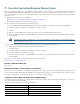
1 Cisco One-Year Limited Hardware Warranty Terms There are special terms applicable to your hardware warranty and various services that you can use during the warranty period. Your formal Warranty Statement, including the warranties and license agreements applicable to Cisco software, is available on Cisco.com. Follow these steps to access and download the Cisco Information Packet and your warranty and license agreements from Cisco.com. 1. Launch your browser, and go to this URL: http://www.cisco.
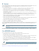
2 Overview The Cisco uBR7246VXR universal broadband router is used in Cisco Cable Modem Termination System (CMTS) solutions. The router allows high-speed data services to be packaged similar to basic cable television service or video fare. The Cisco uBR7246VXR router: • Supports data and packetized voice connectivity over a bidirectional cable television and IP backbone network. • Supports high-speed Internet access, IP telephony, and Virtual Private Network (VPN) applications. • PacketCable 1.
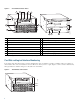
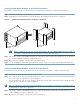
Figure 1 Front and Rear Chassis Views 7 8 6 5 1 7 US DS0 US 7 uBR - MC28U DS0 uBR - MC28U -R -R -R -R DS1 F DS1 F DS1 F DS1 F -R -R -R -R 4 F 12 F F F 9 10 11 103555 7 US DS0 uBR - MC28U 7 6 US 6 US 6 US DS0 uBR - MC28U US 5 US 4 5 4 US US US 4 5 US US 4 5 US 3 2 US 3 2 US 3 US 2 US 3 US 2 US 1 US US US US US US 0 3 1 US US 0 1 US US 0 1 US US 0 2 6 13 1 Internal fans 9 Auxiliary port 2 Clock card 10 Optional Fa
3 Site Preparation Check the following: • Site is capable of maintaining an ambient temperature of 32 to 104 degrees Fahrenheit • Site power is available and adequate • Cabling requirements (type, distance) • Rack-mounting requirements (working space, proper airflow) Site Environment Warning This unit is intended for installation in restricted access areas. A restricted access area can be accessed only through the use of a special tool, lock and key, or other means of security.
Power Connection Guidelines for DC-Powered Systems The DC-input power supply allows the Cisco uBR7246VXR router to operate on either -48 or -60 VDC systems. Warning Connect the unit only to DC power source that complies with the safety extra-low voltage (SELV) requirements in IEC 60950 based safety standards. Statement 1033 The Cisco uBR7246VXR router (using DC power supplies) is not shipped with wiring to connect to a DC power source.
4 Installing the Chassis Rack-Mount Installation Guidelines • Allow sufficient clearance around the rack for maintenance.You need 36 in. (91.44 cm) of clearance to remove and replace system components. • If the Cisco uBR7246VXR chassis is the only unit in a rack, mount the chassis at the bottom of the rack. Use the rack-mount kit that comes with the chassis. • Always place the heavier equipment in the lower half of the rack.
Verifying Contents After Unpacking Power cables, manuals, and other additional items are packaged in separate boxes. After you have unpacked the system, verify that you have received all the required components and documentation. Using the packing list as a guide, verify that you have received everything that is listed, including the following: Step 1 a. System hardware documentation and software documentation (if ordered). b.
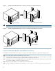
Attach the Rack-Mount Brackets to the Rear of the Chassis To install the rack-mount brackets on the chassis for a rear rack-mount configuration, complete the following steps: Step 1 Locate the threaded holes in the rear sides of the chassis. Step 2 Align the first rack-mount bracket to the threaded holes in the right side of the chassis. See Figure 4.
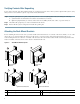
Installing the Rack-Mount Brackets so the Front of the Chassis Is Flush with the Rack 103557 Figure 5 Rack-mount bracket Rack-mount bracket Note Installing the Rack-Mount Brackets so the Front of the Chassis Protrudes Out of the Rack 103558 Figure 6 You cannot use the cable management bracket in this configuration.
Installing the Rack-Mount Brackets in the Middle of the Chassis for Open or Relay-Type Racks Rack-mount bracket Rack-mount bracket 103561 Figure 7 Installing the Cable-Management Brackets If you are rack-mounting the chassis at the rear or middle of the chassis, both rack-mount brackets and the cable-management bracket must be installed before the chassis is installed in the rack. See Figure 8 for cable management bracket locations.
Installing the Chassis in the Rack Warning This unit is intended for installation in restricted access areas. A restricted access area can be accessed only through the use of a special tool, lock and key, or other means of security. Statement 1017 Caution Because the brackets support the weight of the entire chassis, be sure to use all of the required slotted screws to fasten the two rack-mount brackets to the rack posts.
Installing the Chassis on a Workbench or Tabletop Complete the following steps to install the Cisco uBR7246VXR router on a workbench or tabletop: Step 1 Remove any debris and dust from the tabletop or workbench, and the surrounding area. Step 2 On the chassis, ensure that all captive screws on the network processing engine, the I/O controller, the line cards, the clock card, and each power supply are tightened and the port adapter retention clip is in the locked position.
Step 1 Ensure that there is no power going to the router. Step 2 Strip approximately 0.75 in (2 cm) of shielding from the wire. Step 3 Insert the stripped end of the wire into the open end of the ground lug, and crimp the lug. Step 4 Slide a segment of heat shrink tubing over the exposed grounding lug and wire connection. Step 5 Shrink the tubing in place, using a suitable heating device. Step 6 Attach the grounding lug to the router using two M5 hex head screws. See Figure 9 on page 13.
5 Connecting the Chassis to Power Following are the procedures for connecting AC-input or DC-input power to your Cisco uBR7246VXR router. Warning This unit might have more than one power supply connection. All connections must be removed to de-energize the unit. Statement 1028 Warning Take care when connecting units to the supply circuit so that wiring is not overloaded. Statement 1018 Warning This equipment has been designed for connection to TN and IT power systems.
AC Power Supplies Step 1 At the rear of the router, ensure that the power switch on the power supply is in the OFF (0) position. Step 2 Slide the cable-retention clip to the left, away from the AC receptacle, and plug in the power cable. Step 3 Secure the cable in the power supply AC receptacle by sliding the cable-retention clip to the right until it fits around the connector. The cable-retention clip provides strain relief for the AC power cable.
Tools • 8-mm wrench or nut driver, or adjustable wrench (for connecting a grounding lug to a DC-input power supply only) • 7-mm wrench or nut driver, or adjustable wrench (for connecting the DC-input power lead strain-relief cover to a DC-input power supply only) • 14 AWG (2.
Figure 12 Replacing the Strain-Relief Cover on a DC-Input Power Supply Power switch Power receptacle Captive installation screw (on both sides of power supply) Strain-relief cover M5 grounding lug – 48V lead + 48V lead Tip M4 nuts 103573 M5 grounding receptacles Figure 12 shows the grounding lug connected to the two vertically aligned M5 grounding receptacles. You may also connect the grounding lug to the two horizontally aligned M5 receptacles.
6 Powering on the Cisco uBR7246VXR Router Warning Blank faceplates and cover panels serve three important functions: they prevent exposure to hazardous voltages and currents inside the chassis; they contain electromagnetic interference (EMI) that might disrupt other equipment; and they direct the flow of cooling air through the chassis. Do not operate the system unless all cards, faceplates, front covers, and rear covers are in place.
The amplitude and shape of the downstream IF carrier does not change after the router is configured, regardless of modulation scheme used whether 64 or 256-QAM. Tip 20 By default, Cisco uBR-MC16U or Cisco uBR-MC28U cable interface line cards have no output until the DS freq is set and the command no cab down rf-shut is applied.
7 Troubleshooting the Installation This section contains information to help installers and technicians troubleshoot the hardware installation. Figure 13 shows the general troubleshooting strategy used to troubleshoot the hardware. Refer to this flow chart as necessary, and follow the steps to isolate hardware problems to a specific subsystem.
Note If you are using a Cisco uBR7200-NPE-G1, you do not need an I/O controller module installed in the chassis. Use the show version command (Router# show version) to determine the NPE that is installed in your router. 3. If the clock card ENABLED LED is off, verify that the card is securely installed in the chassis. 4. Always verify that the fans are operating.
8 Related Documentation • Cisco uBR7200 Series Universal Broadband Router Hardware Installation Guide, at the following URL: http://www.cisco.com/en/US/products/hw/cable/ps2217/prod_installation_guides_list.html • Field-replaceable units (FRU) information, at the following URL: http://www.cisco.com/en/US/products/hw/cable/ps2217/prod_installation_guides_list.html • Cisco uBR7200 Series Universal Broadband Router Software Configuration Guide, at the following URL: http://www.cisco.
9 Obtaining Documentation and Submitting a Service Request For information on obtaining documentation, submitting a service request, and gathering additional information, see the monthly What’s New in Cisco Product Documentation, which also lists all new and revised Cisco technical documentation, at: http://www.cisco.com/en/US/docs/general/whatsnew/whatsnew.
Americas Headquarters Asia Pacific Headquarters Europe Headquarters Cisco Systems, Inc. San Jose, CA Cisco Systems (USA) Pte. Ltd. Singapore Cisco Systems International BV Amsterdam, The Netherlands Cisco has more than 200 offices worldwide. Addresses, phone numbers, and fax numbers are listed on the Cisco Website at http://www.cisco.com/web/siteassets/contacts/offices/index.html. CCVP, the Cisco logo, and Welcome to the Human Network are trademarks of Cisco Systems, Inc.