
Installation Manual


3-14
Cisco uBR7225VXR Universal Broadband Router Hardware Installation Guide
OL-17309-02
Chapter 3 Installing the Cisco uBR7225VXR Router
Console and Auxiliary Port Connection Equipment
Caution To comply with GR-1089-Core intra-building lightning-immunity requirements, you must use shielded
(screened) cable that is grounded at both ends.
Connecting Cable Interface Line Card Cables
The instructions for connecting the cables for each cable interface line card installed in the
Cisco uBR7225VXR universal broadband router are contained in the cable interface line card
installation document. Refer to the Cisco uBR7200 Series Interface Line Card Hardware Installation
Guide at the following URL:
http://www.cisco.com/en/US/docs/interfaces_modules/cable/line_cards/installation/guide/mcxxfru.htm
l
Console and Auxiliary Port Connection Equipment
The NPE contains the console and auxiliary ports. The console port is a RJ-45 receptacle for connecting
a data terminal, which you use to configure the interfaces and bring up the Cisco uBR7255VXR router.
The auxiliary port is a RJ-45 receptable for connecting a modem or the other DCE device (such as a
channel service unit/data service unit [CSU/DSU]) to the router. (See Figure 3-12 on page 3-14.)
Note Both the console and auxiliary ports are asynchronous ports; any devices connected to these ports must
be capable of asynchronous transmission. (Asynchronous is the most common type of serial device; for
example, most modems are asynchronous devices.)
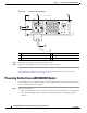
Figure 3-12 Console and Auxiliary Port Connections
1
Console port
3
Console terminal
2
Auxiliary port
4
Modem
272232
4
COMPACT FLASH
GIGABIT ETHERNET 0/1
RJ45 GBIC
EN
RX TX
LINK
CONSOLE AUX
GIGABIT ETHERNET 0/1
RJ45 GBIC
EN
RX TX
LINK
GIGABIT ETHERNET 0/1
RJ45 GBIC
EN
RX TX
LINK
CPU
RESET
POWER
ON
SLOT
ACTIVE
NETWORK PROCESSING ENGINE - G1
1
2
3