
Installation Manual


2-10
Cisco uBR7225VXR Universal Broadband Router Hardware Installation Guide
OL-17309-02
Chapter 2 Preparing the Cisco uBR7225VXR Router for Installation
Provisioning the Cable Headend
• One or more accessories boxes (some or all might be shipped separately)
Step 2 Check the contents of the accessories box against the “Component Checklist” and the packing slip to
verify that you received all listed equipment, which should include the following:
• One modular power cable for an AC-input power supply. (If you purchased a Cisco uBR7225VXR
router with a redundant power supply, you should receive two power cables.)
• One rack-mount and cable-management kit (3 brackets and 14 mounting screws).
• Optional equipment that you ordered, such as network interface cables, transceivers, or special
connectors.
• CNR or CSRC provisioning documentation, or both.
• Cisco IOS software documentation, if ordered.
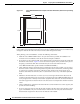
Step 3 Verify that the number of cable interface line cards installed in your Cisco uBR7225VXR router matches
the number of cable interface line cards that you ordered.
Step 4 Refer to Appendix G, “Site Log,” then to the “Cisco uBR7225VXR Router Chassis Rack-Mounting
Options” section on page 3-2 to begin the installation.
Provisioning the Cable Headend
This section describes the necessary preparations to make at the cable headend before you install the
Cisco uBR7225VXR universal broadband router.
Two-Way Data and VoIP
To prepare for two-way data operation, including digitized voice and fax, ensure that the following
conditions are met:
• The cable headend equipment is properly aligned and certified for two-way transmission based on
procedures provided by the manufacturers of the equipment and in accordance with DOCSIS or
EuroDOCSIS RF Interface Specifications.
• The cable headend is wired for narrowcast downstream data transmission.
• The cable headend is wired to supply an RF feed from the upstream fiber-optic receivers to the
Cisco uBR7225VXR router.
• Upstream frequencies are allocated for data transmission.
• Upstream impairments are measured and understood, and comply with recommendations in
DOCSIS or EuroDOCSIS RF interface specifications.
• Upstream ports are configured as appropriate to support frequency agility.
• Downstream frequencies are assigned.
• Internet connectivity is established.
• Internet addresses are obtained and allocated.
• All RF connectivity is verified.