Cisco uBR7225VXR Universal Broadband Router Hardware Installation Guide THE SPECIFICATIONS AND INFORMATION REGARDING THE PRODUCTS IN THIS MANUAL ARE SUBJECT TO CHANGE WITHOUT NOTICE. ALL STATEMENTS, INFORMATION, AND RECOMMENDATIONS IN THIS MANUAL ARE BELIEVED TO BE ACCURATE BUT ARE PRESENTED WITHOUT WARRANTY OF ANY KIND, EXPRESS OR IMPLIED. USERS MUST TAKE FULL RESPONSIBILITY FOR THEIR APPLICATION OF ANY PRODUCTS. Americas Headquarters Cisco Systems, Inc.
THE SOFTWARE LICENSE AND LIMITED WARRANTY FOR THE ACCOMPANYING PRODUCT ARE SET FORTH IN THE INFORMATION PACKET THAT SHIPPED WITH THE PRODUCT AND ARE INCORPORATED HEREIN BY THIS REFERENCE. IF YOU ARE UNABLE TO LOCATE THE SOFTWARE LICENSE OR LIMITED WARRANTY, CONTACT YOUR CISCO REPRESENTATIVE FOR A COPY. The following information is for FCC compliance of Class A devices: This equipment has been tested and found to comply with the limits for a Class A digital device, pursuant to part 15 of the FCC rules.
CONTENTS Document Revision History Document Objectives Audience ix ix x Document Organization x Document Conventions xi Warning Definition xii Obtaining Documentation and Submitting a Service Request CHAPTER 1 Cisco uBR7225VXR Overview xii 1-1 Cisco uBR7225VXR Universal Broadband Router Cisco uBR7225VXR Router Chassis 1-3 1-1 Cisco uBR7225VXR Network Interface Overview 1-4 Card Slot and Logical Interface Numbering 1-4 MAC-Layer Address 1-5 Supported System Configurations Overview Basic Interne
Contents Preventing Electrostatic Discharge Damage 2-4 Site Requirements 2-5 AC Power 2-5 Site Environment 2-5 Site Configuration: Maintaining Normal Operation General Precautions 2-6 Power Considerations 2-7 Required Network Information Before You Begin 2-7 Installation Tools 2-6 2-7 2-8 Rack-Mount and Cable-Management Kit 2-8 Equipment Required to Verify Your Plant’s RF Setup Shipping Container Contents 2-9 Verifying the Shipping Container Contents 2-9 2-9 Provisioning the Cable Headend 2-10 T
Contents Installing Rack-Mount Brackets on the Rear of the Chassis 3-7 Installing Rack-Mount Brackets on the Front of the Chassis 3-8 Installing Rack-Mount Brackets in the Middle of the Chassis 3-9 Installing the Chassis in the Rack 3-10 Installing the Chassis in a Workbench or Tabletop Environment 3-12 Installing the Cable-Management Bracket on a Cisco uBR7225VXR Router in a Workbench or Tabletop Environment 3-13 Cabling 3-13 Connecting Cable Interface Line Card Cables 3-14 Console and Auxiliary Port Co
Contents Measuring the RF Signal at the Forward Test Point on a Laser Transmitter Configuring the Digital Signal CHAPTER 4-40 Maintaining the Cisco uBR7225VXR Router 5 Online Insertion and Removal 5-1 5-1 Environmental Monitoring and Reporting Functions Environmental Monitoring 5-2 Reporting Functions 5-3 Fan Failures 5-6 CHAPTER Troubleshooting 6 4-37 5-2 6-1 Overview 6-1 Providing Information 6-1 Problem Solving with Subsystems 6-2 Identifying Startup Problems 6-3 Power Subsystem 6-4 C
Contents APPENDIX C Cable Specifications Coaxial Cables C-1 C-1 Console and Auxiliary Port Cables and Pinouts Identifying an RJ-45 Rollover Cable C-2 Console Port Cables and Pinouts C-3 Auxiliary Port Cables and Pinouts C-4 C-2 Fast Ethernet Port Cables and Pinouts C-4 Identifying an RJ-45 Crossover Cable C-4 Identifying an RJ-45 Straight-Through Cable Fiber-Optic Cables and Connectors APPENDIX D Industry-Standard Wiring Plans E Frequency Allocation Tables Standards Comparisons D-2 D-2 Telep
Contents Cisco uBR7225VXR Universal Broadband Router Hardware Installation Guide viii OL-17309-02
Preface This preface describes the objectives, intended audience, and organization of this document and explains how to find additional information on related products and services.
Preface Audience This guide is intended for cable system installers and technicians who physically install and connect the Cisco uBR7225VXR universal broadband router and associated equipment at the cable headend or distribution hub. Cable system installers and technicians should be familiar with their cable plant base operating parameters and service offerings. The guide provides limited configuration information.
Preface Appendix F, “Manufacturers for Headend Manufacturers and websites required to prepare and provision a North American Provisioning Requirements” or a European cable headend to support digital data. Appendix G, “Site Log” Example of a cable headend site log—Use to keep a historical record of actions relevant to the Cisco uBR7225VXR router installation, operations, and maintenance.
Preface Timesaver Tip Means the described action saves time. You can save time by performing the action described in the paragraph. Means the following information might help you solve a problem. For all warning translations, refer to the Regulatory Compliance and Safety Information for Cisco uBR7200 Series Universal Broadband Routers at the following URL: http://www.cisco.com/en/US/docs/cable/cmts/ubr7200/regulatory/compliance/ub72rcsi.
CH A P T E R 1 Cisco uBR7225VXR Overview This chapter describes the Cisco uBR7225VXR universal broadband router and contains the following sections: • Cisco uBR7225VXR Universal Broadband Router, page 1-1 • Cisco uBR7225VXR Network Interface Overview, page 1-4 • Supported System Configurations Overview, page 1-6 • Hardware Component Descriptions, page 1-10 Cisco uBR7225VXR Universal Broadband Router The Cisco uBR7200 series universal broadband routers, part of the Cisco Cable Modem Termination Sys
Chapter 1 Cisco uBR7225VXR Overview Cisco uBR7225VXR Universal Broadband Router • A midplane that serves as the interconnect between the cable interface line cards and the other components of the system. See the “Subchassis and Midplane” section on page 1-17. • A fan tray, enclosing internal fans that draw cooling air into the chassis to maintain an acceptable operating temperature. See the “Fan Trays” section on page 1-14.
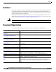
Chapter 1 Cisco uBR7225VXR Overview Cisco uBR7225VXR Universal Broadband Router Cisco uBR7225VXR Router Chassis The Cisco uBR7225VXR router chassis has: • Two slots for cable interface cards • One slot for a network processing engine The front of the Cisco uBR7225VXR chassis provides access to two cable interface line cards. See Figure 1-1. The rear of the Cisco uBR7225VXR provides access to the network processing engine and up to two power supplies. See Figure 1-2.
Chapter 1 Cisco uBR7225VXR Overview Cisco uBR7225VXR Network Interface Overview Cisco uBR7225VXR Router—Rear View Figure 1-2 1 2 3 4 5 uBR7225-VXR 8 7 270490 uBR7225-VXR 6 1 Gigabit Ethernet 0/1 5 Console port 2 Gigabit Ethernet 0/2 6 Auxiliary port 3 Gigabit Ethernet 0/3 7 AC-input power supply 2 4 CompactFlash Disk slot 8 AC-input power supply 1 Cisco uBR7225VXR Network Interface Overview This section provides a functional overview of the network interfaces available on the
Chapter 1 Cisco uBR7225VXR Overview Cisco uBR7225VXR Network Interface Overview US 5 US 7 US 6 US 5 US 4 US 3 US 2 -RF -RF US 1 BLED DS1 uBR - E28U DS0 US 0 ENA uBR7225-VXR ENA 1 Cable interface line card slot 1 2 BLED 270493 US 4 US 3 1 -RF US 2 uBR - E18U DS0 US 1 Cisco uBR7255VXR Chassis and Cable Interface Line Cards US 0 Figure 1-3 2 Cable interface line card slot 2 MAC-Layer Address All LAN interfaces (ports) require unique MAC-layer addresses, also known as hardw
Chapter 1 Cisco uBR7225VXR Overview Supported System Configurations Overview Supported System Configurations Overview The Cisco uBR7200 series universal broadband routers is installed at a cable television headend or a distribution hub. Related networking and RF equipment, servers, and other host computers are installed, along with the Cisco uBR7225VXR router, to support digital data transmission.
Chapter 1 Cisco uBR7225VXR Overview Supported System Configurations Overview – Telco return cable interfaces transmit over the PSTN. Dial-up servers and other equipment handle the upstream traffic and pass appropriate data to the Cisco uBR7225VXR routers. For telco return specifics, refer to the “Telco Return” section on page 1-9. Figure 1-4 shows the architecture of a typical two-way hybrid fiber-coaxial (HFC) network, equipped to support two-way data communication.
Chapter 1 Cisco uBR7225VXR Overview Supported System Configurations Overview VPN Services The Cisco uBR7225VXR router supports VPN services. Figure 1-5 shows a typical VPN architecture. VPNs can be initiated at a cable modem residing at a subscriber site or can be initiated by the CMTS at the headend or distribution hub depending upon your particular Cisco IOS software image.
Chapter 1 Cisco uBR7225VXR Overview Supported System Configurations Overview Figure 1-6 Two-Way IP Telephony Network Example Gateway/PSTN Service provider backbone Cisco uBR7225VXR Gatekeeper or calling agents Remote cable modem Calling party Residence or SOHO* subscriber site 1 Policy server HFC cable plant Remote cable modem Called party Residence or SOHO* subscriber site 2 271652 HFC cable plant Cisco uBR7225VXR *Small Office Home Office Telco Return In telco return configurations, the Ci
Chapter 1 Cisco uBR7225VXR Overview Hardware Component Descriptions Figure 1-7 Telco Return Network Example IP network access Cisco network access server RADIUS dial security server PPP connection between remote cable modem and network access server established following authentication PSTN Upstream IP network Headend or hub Cisco uBR7225VXR HFC downstream including TCD messages Subscriber cable modem 271653 DHCP TFTP TOD servers Hardware Component Descriptions Most Cisco uBR7225VXR universal
Chapter 1 Cisco uBR7225VXR Overview Hardware Component Descriptions • Sending and receiving routing protocol updates • Managing tables, caches, and buffers • Monitoring interface and environmental status • Providing Simple Network Management Protocol (SNMP) management and console/Telnet interface • Accounting and switching of data traffic • Booting and reloading images Refer to Network Processing Engine and Network Services Engine Installation and Configuration, for specifications, and removal
Chapter 1 Cisco uBR7225VXR Overview Hardware Component Descriptions – Cisco uBR7200-NPE-G2—SDRAM: 1 GB (default) and 2 GB. There are two DRAM memory slots, so 1 GB of memory consists of two 512-MB memory SODIMMs, and 2 GB consists of two 1 GB memory SODIMMs. It is necessary to have the same size SODIMM in each memory bank on an NPE-G2. The type of DRAM memory being used on the NPE-G2 is double data-rate (DDR) memory. DDR memory provides high-performance memory access rates.
Chapter 1 Cisco uBR7225VXR Overview Hardware Component Descriptions Power Supplies The Cisco uBR7225VXR router is equipped with one of the following power supplies: Note • 300W AC-input power supply—The maximum AC-input power with single or dual power supply configuration is 300W. The minimum Cisco IOS Release supported on this power supply is the Cisco IOS Release 12.2(33)SCA. • 540W AC-input power supply—The maximum AC-input power with single or dual power supply configuration is less than 700W.
Chapter 1 Cisco uBR7225VXR Overview Hardware Component Descriptions Figure 1-8 Cisco uBR7225VXR AC-Input Power Supply 1 PWR-UBR7225VXR-AC 100-240 VAC 4-2 A 50-60 Hz Input OK 3 Caution Note Output OK 270698 4 2 1 Power switch 3 AC-input receptable 2 Handle 4 Captive installation screw To ensure adequate airflow across the Cisco uBR7225VXR power supplies, a power supply or a power supply filler plate (with its attached air dam) must be installed in each power supply bay.
Chapter 1 Cisco uBR7225VXR Overview Hardware Component Descriptions Temperature sensors on the network processing engine monitor the internal air temperature and send warning messages when the internal air temperature approaches a specified threshold. If the internal temperature exceeds the specified threshold, the system environmental monitor shuts down all internal power to prevent equipment damage from excessive heat. Note The Cisco uBR7225VXR router fan tray is not a field-replaceable unit.
Chapter 1 Cisco uBR7225VXR Overview Hardware Component Descriptions Figure 1-10 Internal Airflow—Top View 1 2 271654 4 3 1 Power supply end 3 Cable interface line card end 2 Inlet flow 4 Exhaust air (fan side) Cisco uBR7225VXR Universal Broadband Router Hardware Installation Guide 1-16 OL-17309-02
Chapter 1 Cisco uBR7225VXR Overview Hardware Component Descriptions Cisco uBR7225VXR Chassis The front of the chassis has two slots for cable interface line cards and one bay for the subchassis. See Figure 1-11.
Chapter 1 Cisco uBR7225VXR Overview Hardware Component Descriptions Figure 1-12 Cisco uBR7225VXR Subchassis and Midplane 1 Top 2 7 3 271655 Back 6 4 5 1 Midplane 5 Power supply receptacle 2 Fan tray slot 6 Captive installations screws (6) 3 Power supply bays 7 Network processing engine slot 4 Fan tray slot CompactFlash Disk The Cisco uBR7225VXR universal broadband router has one CompactFlash Disk slot that uses CompactFlash Disks.
Chapter 1 Cisco uBR7225VXR Overview Hardware Component Descriptions The CompactFlash Disk has controller circuitry that allows it to emulate a hard disk and automatically maps out bad blocks and performs automatic block erasure. The CompactFlash Disk also provides the capability to allocate noncontiguous sectors, which eliminates the need for the squeeze command (which was required with older-style linear flash memory cards to recover the space used by deleted files).
Chapter 1 Cisco uBR7225VXR Overview Hardware Component Descriptions Cisco uBR7225VXR Universal Broadband Router Hardware Installation Guide 1-20 OL-17309-02
CH A P T E R 2 Preparing the Cisco uBR7225VXR Router for Installation This chapter describes the site requirements for installing the Cisco uBR7225VXR universal broadband router and contains the following sections: • Safety Recommendations, page 2-1 • Site Requirements, page 2-5 • Required Network Information, page 2-7 • Installation Tools, page 2-8 • Rack-Mount and Cable-Management Kit, page 2-8 • Equipment Required to Verify Your Plant’s RF Setup, page 2-9 • Shipping Container Contents, pag
Chapter 2 Preparing the Cisco uBR7225VXR Router for Installation Safety Recommendations Warning • Do not wear loose clothing, jewelry (including rings and chains), or other items that could get caught in the chassis. • For systems with installed AC-input power supplies, the Cisco uBR7225VXR router ships with a 3-wire electrical grounding-type plug, which only fits into a grounding-type power outlet. This is a safety feature.
Chapter 2 Preparing the Cisco uBR7225VXR Router for Installation Safety Recommendations Lifting the Chassis (Cisco uBR7246 Router Shown) 271656 Figure 2-1 Warning Two people are required to lift the chassis. Grasp the chassis underneath the lower edge and lift with both hands. To prevent injury, keep your back straight and lift with your legs, not your back.
Chapter 2 Preparing the Cisco uBR7225VXR Router for Installation Safety Recommendations Warning The telecommunications lines must be disconnected 1) before unplugging the main power connector and/or 2) while the housing is open. Statement 89 Warning Before working on a chassis or working near power supplies, unplug the power cord on AC units; disconnect the power at the circuit breaker on DC units.
Chapter 2 Preparing the Cisco uBR7225VXR Router for Installation Site Requirements Caution • Ensure that the network processing engine is fully inserted in its chassis slot and the captive installation screws are tightened. The captive installation screws prevent accidental removal, provide proper grounding for the system, and help ensure that the bus connectors are seated in the midplane.
Chapter 2 Preparing the Cisco uBR7225VXR Router for Installation Site Requirements To provide airflow through the Cisco uBR7225VXR router, cooling air is drawn in through the air intake vent on the right side of the chassis (when viewing the router from the front) and is exhausted through the left side of the chassis. Keep the right and left sides of the chassis clear of obstructions and away from the exhaust of other equipment.
Chapter 2 Preparing the Cisco uBR7225VXR Router for Installation Required Network Information • Ensure that the network processing engine, cable interface line cards, any blank cable interface line cards, power supplies, and any power supply filler plates are in place and secure. The fans direct cooling air throughout the chassis interior; a loose component or empty slot can redirect the airflow away from active components and cause overheating.
Chapter 2 Preparing the Cisco uBR7225VXR Router for Installation Installation Tools • IP addresses and subnet masks, if you are routing IP. • Dial-up access telephone numbers, usernames, and passwords for telco return operation. • RADIUS security and accounting configuration. • Gateway and gatekeeper zone configuration for your H.323 VoIP network. • Gateway and call-agent configuration for your SGCP VoIP network.
Chapter 2 Preparing the Cisco uBR7225VXR Router for Installation Equipment Required to Verify Your Plant’s RF Setup Equipment Required to Verify Your Plant’s RF Setup To verify your plant’s RF setup, you need the following: • RF spectrum analyzer • For coaxial cabling: – Diplex filters/splitters – Coaxial cable crimping tool – New coaxial cable – Coaxial jumpers that are at least 2 to 3 feet long (maximum of 5 feet) Note • For fiber networks, optical receivers for each upstream optical path • Asso
Chapter 2 Preparing the Cisco uBR7225VXR Router for Installation Provisioning the Cable Headend • Step 2 One or more accessories boxes (some or all might be shipped separately) Check the contents of the accessories box against the “Component Checklist” and the packing slip to verify that you received all listed equipment, which should include the following: • One modular power cable for an AC-input power supply.
Chapter 2 Preparing the Cisco uBR7225VXR Router for Installation Provisioning the Cable Headend Note For a VoIP system using H.323, ensure that the CMTS has been properly provisioned with equipment such as VoIP gateways and gatekeepers. For SGCP-based VoIP systems, ensure that the CMTS has been properly provisioned with equipment such as VoIP gateways and call-agents.
Chapter 2 Preparing the Cisco uBR7225VXR Router for Installation Provisioning the Cable Headend DHCP, DNS, TFTP, and TD Servers A DHCP server must be installed at the headend. The DHCP server must also offer a time-of-day (TD) server option that is compliant with RFC 868. In conjunction with the DHCP server, a Domain Name System (DNS) server must be installed to translate names of network nodes into IP addresses.
Chapter 2 Preparing the Cisco uBR7225VXR Router for Installation Provisioning the Cable Headend Figure 2-2 Servers on an HFC Network Log server (optional) Security Cisco Network server Registrar DHCP/DNS server (optional) Cisco uBR7225VXR Remote Cisco 7500 access server* series router Time-of-day server TFTP server *A remote access server is required on an HFC network only when you want to offer VoIP using H.323 or telco return service.
Chapter 2 Preparing the Cisco uBR7225VXR Router for Installation Provisioning the Cable Headend Headend Wiring This section provides guidelines for setting up the headend wiring and cabling at your site. When planning the location of the new system, consider the distance limitations for signaling, EMI, and connector compatibility, as described in the following sections.
Chapter 2 Preparing the Cisco uBR7225VXR Router for Installation Provisioning the Cable Headend • Any additional interface equipment you need, such as transceivers, hubs, switches, modems, channel service units (CSUs), or data service units (DSUs) • Cable pinouts if you plan to build your cables Before installing the Cisco uBR7225VXR router, have all additional external equipment and cables available. The information listed above is available at Cisco.com.
Chapter 2 Preparing the Cisco uBR7225VXR Router for Installation Provisioning the Cable Headend Figure 2-3 Cisco uBR7225VXR Router Footprint and Outer Dimensions (View from Top Looking Down) 17.32 in. 21.875 in. 271658 23.875 in.
Chapter 2 Preparing the Cisco uBR7225VXR Router for Installation Site Preparation Checklist • Install and use the cable-management bracket included with the Cisco uBR7225VXR rack-mount kit to keep cables organized. Consider the equipment and cabling that is already installed in the rack. Ensure that cables from other equipment will not impair access to the interface slots, or require you to disconnect cables unnecessarily to perform equipment maintenance or upgrades.
Chapter 2 Preparing the Cisco uBR7225VXR Router for Installation Component Checklists Table 2-2 Site Preparation Checklist (continued) Task Verified By Date Gatekeeper and gateway equipment installed and configured. Dial plan based on the supported VoIP protocol used—H.323 or SGCP. Component Checklists • Check off the equipment as it is unpacked. • Titles and quantities of documents will vary.
CH A P T E R 3 Installing the Cisco uBR7225VXR Router This chapter explains how to install and connect a Cisco uBR7225VXR universal broadband router and contains the following sections: • Cisco uBR7225VXR Router Installation Checklist, page 3-1 • Cisco uBR7225VXR Router Chassis Rack-Mounting Options, page 3-2 • Installing the Brackets on the Chassis, page 3-7 • Installing the Chassis in a Workbench or Tabletop Environment, page 3-12 • Cabling, page 3-13 • Console and Auxiliary Port Connection E
Chapter 3 Installing the Cisco uBR7225VXR Router Cisco uBR7225VXR Router Chassis Rack-Mounting Options Table 3-1 Cisco uBR7225VXR Router Installation Checklist Task Verified by Date Router and all accessories unpacked Types and numbers of interfaces verified Verify shipping container contents see the “Shipping Container Contents” section on page 2-9 Router mounted in rack (optional) Cable-management bracket installed (optional but recommended) Chassis properly grounded AC power cables connected to p
Chapter 3 Installing the Cisco uBR7225VXR Router Cisco uBR7225VXR Router Chassis Rack-Mounting Options Figure 3-1 Typical 4-Post Equipment Rack Posts and Mounting Strips Rack posts 110 VAC outlets 18.31 in. (46.48 cm) hole center-to-center 10327 Mounting strips 17.5 in. (44.45 cm) min.
Chapter 3 Installing the Cisco uBR7225VXR Router Cisco uBR7225VXR Router Chassis Rack-Mounting Options Installing the Chassis in a 4-Post Rack—Rear Installation 271659 Figure 3-2 1 1 Rack-mount bracket See the “Installing Rack-Mount Brackets on the Rear of the Chassis” section on page 3-7.
Chapter 3 Installing the Cisco uBR7225VXR Router Cisco uBR7225VXR Router Chassis Rack-Mounting Options Installing the Chassis in a 4-Post Rack—Chassis Protruding Front Installation 271661 Figure 3-4 1 1 Rack-mount bracket See the “Installing Rack-Mount Brackets in the Middle of the Chassis” section on page 3-9 for bracket mounting information.
Chapter 3 Installing the Cisco uBR7225VXR Router Cisco uBR7225VXR Router Chassis Rack-Mounting Options In the second configuration, for a telco-type rack, the rack-mount brackets are installed at the middle of the chassis and the cable-management bracket is installed at the right front of the chassis. (See Figure 3-7.) You must install both sets of brackets before you install the chassis in the rack.
Chapter 3 Installing the Cisco uBR7225VXR Router Installing the Brackets on the Chassis Installing the Brackets on the Chassis This section explains how to install the rack-mount brackets and cable-management bracket on a Cisco uBR7225VXR universal broadband router. Before installing the chassis in the rack, you must install cable-management bracket and a rack-mount bracket on each side of the front, middle, or rear of the chassis.
Chapter 3 Installing the Cisco uBR7225VXR Router Installing the Brackets on the Chassis Step 6 Thread two M3 x 6-mm Phillips panhead screws through the cable-management bracket and into the chassis, and tighten the screws. This completes the procedure for installing the rack-mount brackets and the cable-management bracket on the chassis for a rear rack-mount configuration. Proceed to the “Installing the Chassis in the Rack” section on page 3-10.
Chapter 3 Installing the Cisco uBR7225VXR Router Installing the Brackets on the Chassis Installing the Rack-Mount Brackets so the Front of the Chassis Protrudes Out of the Rack 271667 Figure 3-10 1 1 Rack-mount bracket Step 3 Thread four M4 x 6-mm Phillips flathead screws through the rack-mount bracket and into the side of the chassis. Use a number 2 Phillips screwdriver to tighten the screws. Step 4 Repeat Step 1 through Step 3 for the other rack-mount bracket.
Chapter 3 Installing the Cisco uBR7225VXR Router Installing the Brackets on the Chassis Installing the Rack-Mount Brackets in the Middle of the Chassis for Telco-Type Racks 271668 Figure 3-11 1 1 Rack-mount bracket Step 3 Thread four M4 x 6-mm Phillips flathead screws through the rack-mount bracket and into the side of the chassis. Use a number 2 Phillips screwdriver to tighten the screws. Step 4 Repeat Step 1 through Step 3 for the other rack-mount bracket.
Chapter 3 Installing the Cisco uBR7225VXR Router Installing the Brackets on the Chassis Caution Because the brackets support the weight of the entire chassis, be sure to use all of the required slotted screws to fasten the two rack-mount brackets to the rack posts. Figure 3-2 on page 3-4, Figure 3-3 on page 3-4, Figure 3-4 on page 3-5, and Figure 3-5 on page 3-5 show typical installations in 19-inch, four-post and telco-type equipment racks. Warning Two people are required to lift the chassis.
Chapter 3 Installing the Cisco uBR7225VXR Router Installing the Chassis in a Workbench or Tabletop Environment Step 6 Insert the 10/32 x 3/8 slotted screws (two to a side) through the brackets and into the mounting strip (use the top and bottom bracket holes, shown in Figure 3-2 on page 3-4, Figure 3-3 on page 3-4, Figure 3-4 on page 3-5, and Figure 3-5 on page 3-5). Using a 7/16-inch flat-blade screwdriver, tighten all the screws. This completes the procedure for installing the chassis in the rack.
Chapter 3 Installing the Cisco uBR7225VXR Router Cabling Step 3 Add the five rubber feet supplied with the accessory kit to the base of the chassis. Five indented circles are provided on the base of the chassis to indicate the location to which the rubber feet can be added. Step 4 Place the Cisco uBR7225VXR router on the tabletop or workbench. Step 5 Ensure that there is the appropriate amount of space around the router.
Chapter 3 Installing the Cisco uBR7225VXR Router Console and Auxiliary Port Connection Equipment Caution To comply with GR-1089-Core intra-building lightning-immunity requirements, you must use shielded (screened) cable that is grounded at both ends. Connecting Cable Interface Line Card Cables The instructions for connecting the cables for each cable interface line card installed in the Cisco uBR7225VXR universal broadband router are contained in the cable interface line card installation document.
Chapter 3 Installing the Cisco uBR7225VXR Router Console and Auxiliary Port Connection Equipment Before connecting a terminal to the console port, configure the terminal to match the Cisco uBR7225VXR router console port as follows: • 9600 baud • 8 data bits • No parity • 1 stop bit (9600 8N1) You need an RJ-45 console cable to connect the terminal to the console port. After you establish normal universal broadband router operation, you can disconnect the terminal.
Chapter 3 Installing the Cisco uBR7225VXR Router Protective Grounding Table 3-3 Auxiliary Port Signals Pin Signal Direction Description 8 CD <— Carrier Detect (used for modem control) 20 DTR —> Data Terminal Ready (used for modem control only) Protective Grounding The building installation should provide a means for connection to the protective earth grounding. The equipment should be connected to that means.
Chapter 3 Installing the Cisco uBR7225VXR Router Connecting Power Warning Before working on equipment that is connected to power lines, remove jewelry (including rings, necklaces, and watches). Metal objects will heat up when connected to power and ground and can cause serious burns or weld the metal object to the terminals. Statement 43 Warning This equipment is intended to be grounded to comply with emission and immunity requirements.
Chapter 3 Installing the Cisco uBR7225VXR Router Powering On the Cisco uBR7225VXR Router Figure 3-14 Connecting AC-Input Power 1 2 PWR-UBR7225VXR-AC 5 100-240 VAC 4-2 A 50-60 Hz Input Output OK OK 271670 4 3 1 Power switch 4 Power receptacle 2 Handle 5 Captive installation screw 3 AC power cable Step 3 Plug the AC power supply cable into the AC power source. Step 4 Repeat Step 1 through Step 3 for the second power supply (if present).
Chapter 3 Installing the Cisco uBR7225VXR Router Configuring the Interfaces Note If the cable interface line card or the network processing engine is not properly seated or not fully locked into place, the Cisco uBR7225VXR router might enter a continuous restart loop. Make sure that the boards are seated and locked into position. • Hybrid fiber-coaxial (HFC) network coaxial cable is connected to the cable interface line cards.
Chapter 3 Installing the Cisco uBR7225VXR Router Configuring the Interfaces At any point you may enter a questions mark ‘?’ for help. Use ctrl-c to abort configuration dialof at any prompt. Default settings are in square brackets ‘[]’. continue with configuration dialog? [yes]: You can proceed with the setup facility or exit from the setup facility, using the command interface to configure global (system-wide) and interface-specific parameters.
CH A P T E R 4 Connecting the Cisco uBR7225VXR Router to the Cable Headend This chapter describes how to connect the Cisco uBR7225VXR universal broadband router to a cable headend and contains the following sections: Note • Two-Way Data Headend Architecture, page 4-2 • One-Way Data Headend Architecture, page 4-3 • RF and Digital Data Overview, page 4-3 • Connecting and Configuring the Downstream, page 4-4 • Measuring the Downstream RF Signal, page 4-4 • Connecting and Configuring the Upstream
Chapter 4 Connecting the Cisco uBR7225VXR Router to the Cable Headend Two-Way Data Headend Architecture Two-Way Data Headend Architecture Figure 4-1 shows a typical headend configuration configured for two-way data, including digitized voice and fax.
Chapter 4 Connecting the Cisco uBR7225VXR Router to the Cable Headend One-Way Data Headend Architecture One-Way Data Headend Architecture Figure 4-2 shows a typical headend configuration configured for one-way (downstream) data in a telco return cable system.
Chapter 4 Connecting the Cisco uBR7225VXR Router to the Cable Headend Connecting and Configuring the Downstream • Noise funneling—The upstream data path to the headend is susceptible to picking up noise and interference from anywhere in the network, and all upstream noise ultimately ends up at the headend. This effect is known as noise funneling because of the cumulative nature of the noise from one or more locations in the network that becomes concentrated at the headend.
Chapter 4 Connecting the Cisco uBR7225VXR Router to the Cable Headend Measuring the Downstream RF Signal These two sections describe the procedures necessary to use a spectrum analyzer. You may also use a signal level meter that has the ability to measure the average power level of digitally modulated carriers, as well as a QAM analyzer. Some instruments to perform these measurements include: • Acterna SDA-5000 w/Option 4 (http://www.acterna.com) • Agilent 8591C, N1776A, 2010 or 3010 (http://www.tm.
Chapter 4 Connecting the Cisco uBR7225VXR Router to the Cable Headend Measuring the Downstream RF Signal Figure 4-3 Step 5 Measure the IF signal using the channel power option on your spectrum analyzer. Set your channel spacing and your channel bandwidth to 6 MHz. Your analyzer should display a signal similar to the one shown in Figure 4-4. Figure 4-4 Note Step 6 Viewing the Downstream IF Signal on a Spectrum Analyzer Measuring the IF Channel Power The IF channel power in Figure 4-4 is +34.
Chapter 4 Connecting the Cisco uBR7225VXR Router to the Cable Headend Measuring the Downstream RF Signal Figure 4-5 Note Measuring the IF Channel Power Using Video Averaging The approximate in-channel peak-to-valley flatness may be verified using the spectrum analyzer’s video averaging feature. Be aware, however, that amplitude values registered while in the video averaging mode are typically around 2.5 dB below the actual channel power.
Chapter 4 Connecting the Cisco uBR7225VXR Router to the Cable Headend Measuring the Downstream RF Signal Figure 4-6 Overloaded Spectrum Analyzer Input Step 4 Set the input of the upconverter to a digital QAM signal and the output level to the manufacturer’s recommended settings. Typical output amplitudes range from +50 to +58 dBmV, although DOCSIS specifies +61 dBmV. Step 5 Set the spectrum analyzer to view the RF signal at the center frequency you selected for your headend.
Chapter 4 Connecting the Cisco uBR7225VXR Router to the Cable Headend Measuring the Downstream RF Signal Figure 4-8 Measuring the RF Signal at the Upconverter Output—Overload Condition Corrected with Attenuation Step 7 Change the spectrum analyzer settings to view the digital channel power. This setting enables you to see if there is too much power on the upconverter output. In Figure 4-9, the upconverter output is reading +64.31 dBmV, which is beyond the DOCSIS-specified range of +50 to +61 dBmV.
Chapter 4 Connecting the Cisco uBR7225VXR Router to the Cable Headend Measuring the Downstream RF Signal Figure 4-10 Step 9 Select the video averaging feature on the spectrum analyzer. The signal becomes smoother and frequency response problems might become visible. Your analyzer now displays an RF signal similar to the one shown in Figure 4-11.
Chapter 4 Connecting the Cisco uBR7225VXR Router to the Cable Headend Measuring the Downstream RF Signal Step 10 Verify that your headend RF measurements meet the recommended DOCSIS parameters listed in the tables in Appendix B, “RF Specifications.” Record your headend settings and measurements in your headend site log (Appendix G, “Site Log”). This will assist in troubleshooting the Cisco uBR7225VXR router installation later in the process.
Chapter 4 Connecting the Cisco uBR7225VXR Router to the Cable Headend Measuring the Downstream RF Signal Figure 4-12 Step 4 Advance to the last of the three screens in this display. Your analyzer should display a signal similar to the one shown in Figure 4-13.
Chapter 4 Connecting the Cisco uBR7225VXR Router to the Cable Headend Measuring the Downstream RF Signal Figure 4-14 Step 6 Using the spectrum analyzer’s reference level control, adjust the amplitude of the displayed signal until the shape of the signal is clearly distinguishable as a digitally modulated carrier, as shown in Figure 4-15.
Chapter 4 Connecting the Cisco uBR7225VXR Router to the Cable Headend Measuring the Downstream RF Signal Figure 4-16 Note Measuring the IF Signal on a Spectrum Analyzer in CATV Mode—Digital Channel Power Screen (Using Video Averaging) The approximate in-channel peak-to-valley flatness can be verified using the spectrum analyzer’s video averaging feature. Be aware, however, that amplitude values registered while in the video averaging mode are typically around 2.5 dB below the actual channel power.
Chapter 4 Connecting the Cisco uBR7225VXR Router to the Cable Headend Measuring the Downstream RF Signal Figure 4-17 Step 7 Advance to the last of the three screens in this display. Your analyzer should display a signal similar to the one shown in Figure 4-18.
Chapter 4 Connecting the Cisco uBR7225VXR Router to the Cable Headend Measuring the Downstream RF Signal Figure 4-19 Step 9 Using the spectrum analyzer’s reference level control, adjust the amplitude of the displayed signal until the signal peak is within the top graticule of the analyzer’s display grid, as shown in Figure 4-20.
Chapter 4 Connecting the Cisco uBR7225VXR Router to the Cable Headend Measuring the Downstream RF Signal Figure 4-21 Note Measuring the RF Signal at the Upconverter Output in CATV Mode—Digital Channel Power Screen Using Video Averaging The approximate in-channel peak-to-valley flatness can be verified using the spectrum analyzer’s video averaging feature. Be aware, however, that amplitude values registered while in the video averaging mode are typically around 2.5 dB below the actual channel power.
Chapter 4 Connecting the Cisco uBR7225VXR Router to the Cable Headend Connecting and Configuring the Upstream Connecting and Configuring the Upstream The following sections describe how to connect and configure the upstream for digital data. Connecting the Upstream to the Optical Receiver To connect the upstream to the optical receiver, use a 2-way splitter as a combiner to leave the DOCSIS cable modem connected at the headend, and connect the upstream headend cable to the optical receiver.
Chapter 4 Connecting the Cisco uBR7225VXR Router to the Cable Headend Connecting and Configuring the Upstream Figure 4-22 Connecting and Configuring the Upstream Cisco uBR7225VXR X-level test point signal level must be the same for all optical receivers (+/- 0.5 dB), See Fig.
Chapter 4 Connecting the Cisco uBR7225VXR Router to the Cable Headend Connecting and Configuring the Upstream This “X-level” test point measurement will be different for every fiber node in the HFC network until you adjust the attenuation on the upstream. You must adjust the attenuation so that this measurement is the same on every fiber node. If you change a receiver or a transmitter at the fiber node, or if you unplug a connector and plug it back in, you must recheck this amplitude measurement.
Chapter 4 Connecting the Cisco uBR7225VXR Router to the Cable Headend Connecting and Configuring the Upstream Figure 4-25 Calibrating Multiple “X-level” Test Points Connected to Multiple Upstream Ports Cisco uBR7225VXR Downstream Upstream 0 dBmV +10 dBmV 2-way splitter 6 dB attenuator X +13 dBmV 3 dB attenuator Reverse optical Optical receiver Fiber-optic transmitter +17 dBmV cable Diplex filter 40 dB attenuator L H Downstream (0 to +5 dBmV) Cable modems +31 dBmV Distribution +48 dBmV network
Chapter 4 Connecting the Cisco uBR7225VXR Router to the Cable Headend Measuring the Upstream RF Signal Measuring the Upstream RF Signal You can use a spectrum analyzer to measure the upstream signal from one or more remote cable modems in a two-way data cable network. Performing this procedure can help alert you to potential problems in your cable network’s upstream configuration before a problem occurs.
Chapter 4 Connecting the Cisco uBR7225VXR Router to the Cable Headend Measuring the Upstream RF Signal Figure 4-26 Tip Step 6 Note The horizontal line passing through the center of the spectrum analyzer display in Figure 4-26 is the trigger line. Set the sweep value to 80 microseconds. Your spectrum analyzer should display a signal similar to the one shown in Figure 4-27. Be sure that your particular spectrum analyzer is capable of supporting sweep times as short as 80 microseconds.
Chapter 4 Connecting the Cisco uBR7225VXR Router to the Cable Headend Measuring the Upstream RF Signal Note Refer to the documentation that accompanied your particular spectrum analyzer for detailed instructions on activating and positioning the trigger line. A known workaround exists for the Agilent 8591C spectrum analyzer. After activating and positioning the trigger line in video mode, you must press the “video” button on the spectrum analyzer once more to enable proper functionality.
Chapter 4 Connecting the Cisco uBR7225VXR Router to the Cable Headend Measuring the Upstream RF Signal Step 10 Verify that your headend RF measurements meet the recommended DOCSIS parameters listed in the tables in Appendix B, “RF Specifications.” Step 11 Record your headend settings in Appendix G, “Site Log.” This will assist in troubleshooting the Cisco uBR7225VXR universal broadband router installation later in the process.
Chapter 4 Connecting the Cisco uBR7225VXR Router to the Cable Headend Measuring the Upstream RF Signal Figure 4-30 Note Analyzing the Upstream RF Signal—1500-Byte Data Packets Both of the previous examples feature 16-QAM transmission with a channel width of 3.2 MHz, yielding a 10-Mbit/sec data rate. In addition, these examples have an optimal upstream carrier-to-noise ratio of approximately 50 dB. Now it is time to view your upstream RF signal with multiple remote cable modems.
Chapter 4 Connecting the Cisco uBR7225VXR Router to the Cable Headend Measuring the Upstream RF Signal Note Figure 4-31 Analyzing the Upstream RF Signal—Multiple Active Remote Cable Modems (A) Figure 4-32 Analyzing the Upstream RF Signal—Multiple Active Remote Cable Modems (B) When viewing the upstream RF signal on your spectrum analyzer, two ping packet returns (for example, from remote cable modems A and B) can be so close together that they appear to be one rather large packet with a slight jump o
Chapter 4 Connecting the Cisco uBR7225VXR Router to the Cable Headend Measuring the Upstream RF Signal The importance of this example is to bring to your attention the need for minimal outside plant noise. Time-varying, fast noise can cause bit errors in packet transmissions, rendering your communication link unreliable, if not unusable.
Chapter 4 Connecting the Cisco uBR7225VXR Router to the Cable Headend Measuring the Upstream RF Signal Step 1 Display a signal complete with preamble and upstream data transmission information similar to the resulting signal from Step 3 through Step 10 under the “Measuring the Upstream RF Signal Using a Spectrum Analyzer” section on page 4-22. Your spectrum analyzer should display a signal similar to the one in Figure 4-34.
Chapter 4 Connecting the Cisco uBR7225VXR Router to the Cable Headend Measuring the Upstream RF Signal Figure 4-35 Vector Signal Analyzer Plot of Upstream Data Burst The upper graph in Figure 4-35 represents the frequency domain and the lower graph represents the time domain. In the time domain, the channel power of the preamble of a digital upstream signal is not spread across the entire channel.
Chapter 4 Connecting the Cisco uBR7225VXR Router to the Cable Headend Measuring the Upstream RF Signal Figure 4-36 Vector Signal Analyzer Plot of Upstream Data Burst (Preamble Only) Figure 4-35 and Figure 4-36 illustrate the benefit of properly adjusting the center frequency of your spectrum analyzer to enable the power measurement of the preamble to match the power measurement of the rest of the digital transmission.
Chapter 4 Connecting the Cisco uBR7225VXR Router to the Cable Headend Measuring the Upstream RF Signal Figure 4-37 d. Vector Signal Analyzer Plot of Upstream Data Burst (Preamble Only)—QPSK Demodulation Mode Switch your vector signal analyzer over to quaternary phase shift keying (QPSK) demodulation mode. Your vector signal analyzer will display a set of screens similar to those in Figure 4-38. Figure 4-38 displays the QPSK demodulation information for the same upstream signal as in Figure 4-37.
Chapter 4 Connecting the Cisco uBR7225VXR Router to the Cable Headend Measuring the Upstream RF Signal Figure 4-38 Note Step 3 Vector Signal Analyzer Plot of Upstream Data Burst (Preamble Only)—Digital Demodulation Mode Before moving on to Step 3, be sure to hook your spectrum analyzer back up to the upstream signal source. On your spectrum analyzer, narrow both the resolution and video bandwidth to 1 MHz.
Chapter 4 Connecting the Cisco uBR7225VXR Router to the Cable Headend Measuring the Upstream RF Signal Figure 4-39 Note Step 4 Preamble Amplitude Before Center Frequency Adjustment The slight amplitude variations shown in these figures are normal signal level variations between bursts in the upstream channel. Expect modems to vary upstream transmit power by nearly 1 dB between bursts. This is well within the requirements for DOCSIS compliance. The default variation between modems is up to 1.
Chapter 4 Connecting the Cisco uBR7225VXR Router to the Cable Headend Measuring the Upstream RF Signal Figure 4-40 Preamble Amplitude Recovery After Center Frequency Adjustment To get an even better look at the patterns and dramatic shifts in amplitude within the preamble itself, you can accelerate the sweep time for your zero-span signal processing. Step 6 Tune the spectrum analyzer to the original center frequency (32.608 MHz in this example).
Chapter 4 Connecting the Cisco uBR7225VXR Router to the Cable Headend Measuring the Upstream RF Signal Note The 4.25 dB decrease in amplitude is due to a combination of half of the channel bandwidth (3 dB) and an additional 1.25 dB decrease attributed to the digital channel filter mask, known as the “alpha.” The value of alpha is 25 percent of an upstream DOCSIS channel’s width, and the peak signal energy spread across the entire upstream channel width.
Chapter 4 Connecting the Cisco uBR7225VXR Router to the Cable Headend Measuring the RF Signal at the Forward Test Point on a Laser Transmitter Note The slight “ramp-up” at the beginning of the preamble when viewed in this mode is attributed to the time required to charge the spectrum analyzer’s detector circuit. Figure 4-43 shows a smooth and easily measured signal amplitude, providing accurate measurement of a very fast burst upstream carrier.
Chapter 4 Connecting the Cisco uBR7225VXR Router to the Cable Headend Measuring the RF Signal at the Forward Test Point on a Laser Transmitter Figure 4-45 Step 3 Downstream Forward Test Point on the Laser Transmitter—Video Channel Display Select the carrier level (or amplitude) function. Figure 4-46 shows the detailed display of the analog carrier level and frequency screen for the channel 48 (in this example).
Chapter 4 Connecting the Cisco uBR7225VXR Router to the Cable Headend Measuring the RF Signal at the Forward Test Point on a Laser Transmitter Figure 4-47 Step 6 Go to the main menu on the spectrum analyzer and advance the screen displays (next screen) until the digital channel power display is shown. (See Figure 4-48.
Chapter 4 Connecting the Cisco uBR7225VXR Router to the Cable Headend Configuring the Digital Signal Step 8 Select the video averaging feature to verify flatness through the headend combiner. After 10 averages, the power rating decreases by approximately 2.5 dB from actual digital channel power. While video averaging is in progress, your spectrum analyzer should display a signal similar to the one shown in Figure 4-49.
Chapter 4 Connecting the Cisco uBR7225VXR Router to the Cable Headend Configuring the Digital Signal Careful system design and operation can prevent potentially serious intermittent performance problems across your cable interface network. Each cable operator should make use of the following guidelines and practices to ensure reliable operation of any 64-QAM based digital network: • “NCTA Recommended Practices for Measurements on Cable Television Systems” (http://www.ncta.
Chapter 4 Connecting the Cisco uBR7225VXR Router to the Cable Headend Configuring the Digital Signal Cisco uBR7225VXR Universal Broadband Router Hardware Installation Guide 4-42 OL-17309-02
CH A P T E R 5 Maintaining the Cisco uBR7225VXR Router This chapter describes basic maintenance for the Cisco uBR7225VXR universal broadband router and contains the following sections: • Online Insertion and Removal, page 5-1 • Environmental Monitoring and Reporting Functions, page 5-2 Online Insertion and Removal The cable interface line cards and network processing engine in the Cisco uBR7225VXR universal broadband router support online insertion and removal (OIR).
Chapter 5 Maintaining the Cisco uBR7225VXR Router Environmental Monitoring and Reporting Functions Caution The network processing engine cannot be removed if the router is operating. Removing the network processing engine while the Cisco uBR7225VXR router is operating causes the router to shut down or crash, and might damage or destroy memory files. Each cable interface line card has a bus connector that connects it to the router’s midplane.
Chapter 5 Maintaining the Cisco uBR7225VXR Router Environmental Monitoring and Reporting Functions • Shutdown—The processor has detected a temperature condition that could result in physical damage to system components and has disabled DC power to all internal components. Requires immediate operator action. Before any shutdown, the system logs the status of monitored parameters in NVRAM so that you can retrieve it later to help determine the cause of the problem.
Chapter 5 Maintaining the Cisco uBR7225VXR Router Environmental Monitoring and Reporting Functions Caution To prevent overheating the chassis, ensure that your system is drawing cool inlet air. Overtemperature conditions can occur if the system is drawing in the exhaust air of other equipment.
Chapter 5 Maintaining the Cisco uBR7225VXR Router Environmental Monitoring and Reporting Functions The show environment table command displays the temperature and voltage thresholds for each temperature sensor and for each monitored status level, which are related to those thresholds listed in Table 5-1. The display also lists the shutdown threshold for the system. You can abbreviate the command to sh env table.
Chapter 5 Maintaining the Cisco uBR7225VXR Router Environmental Monitoring and Reporting Functions Voltage readings: +3.30 V measured at +3.28 V +1.50 V measured at +1.49 V +2.50 V measured at +2.48 V +1.80 V measured at +1.78 V +1.20 V measured at +1.19 V VDD_CPU measured at +1.27 V VDD_MEM measured at +2.48 V VTT measured at +1.24 V +3.45 V measured at +3.49 V -11.95 measured at -11.79 V +5.15 V measured at +5.00 V +12.15 V measured at +11.71 V +1.2 V(MP NPE) measured at +1.19 V +1.
CH A P T E R 6 Troubleshooting This chapter provides troubleshooting information for the Cisco uBR7225VXR universal broadband router and contains the following sections: • Overview, page 6-1 • Problem Solving with Subsystems, page 6-2 • Power Subsystem, page 6-4 • Cooling Subsystem, page 6-4 • Processor Subsystem, page 6-5 • Verifying the Downstream Signal, page 6-7 Overview This chapter contains instructions to help installers and technicians troubleshoot hardware installation.
Chapter 6 Troubleshooting Problem Solving with Subsystems Troubleshooting Strategy for Startup Problems Turn on system power DC OK LED on? No Troubleshoot power subsystem DC OK LED on? Yes Fans operating? Check system state with interface card LEDs End No Cable interface card LEDs OK? Reseat cable interface cards and restart No Interface card LEDs OK? Check the headend setup End No Digital data connections enabled? Yes Troubleshoot headend setup for RF and data No Digital data connect
Chapter 6 Troubleshooting Problem Solving with Subsystems • Cable headend subsystem—External to the Cisco uBR7225VXR router, this subsystem can prevent operation of the universal broadband router if the headend is not properly set up for the introduction of digital data into the hybrid fiber-coaxial (HFC) network. The following section helps you isolate a problem to one of the subsystems and directs you to the appropriate troubleshooting section.
Chapter 6 Troubleshooting Power Subsystem Power Subsystem Check the following to help isolate a problem with the power subsystem: Step 1 Toggle the power supply switch off and on. Step 2 On the first power supply, is the Input OK LED on? Step 3 Step 4 a. If yes, the power source is good, and the power supply is functional. b. If not, make sure that the power cable is connected at both ends. Then toggle the power switch off and on.
Chapter 6 Troubleshooting Processor Subsystem To determine if the fans are operating, listen for them. In noisy environments, place your hand on the left side of the chassis (when viewing the chassis from the front) to feel for air being forced out the vents. Step 2 a. If yes, the power to the fan tray is good. b. If no, there is a problem with the fan tray or power. See the “Power Subsystem” section on page 6-4. Verify that the following message is not displayed.
Chapter 6 Troubleshooting Processor Subsystem Step 2 b. Reseat the network processing engine in its slot. c. Restart the router. Verify that you are running a version of Cisco IOS software that supports the NPE you are using: a. For the latest Cisco IOS software release information, refer to the Cisco uBR7200 series release notes at the following URL: http://www.cisco.com/en/US/products/hw/cable/ps2217/prod_release_notes_list.html Step 3 b.
Chapter 6 Troubleshooting Verifying the Downstream Signal Other Troubleshooting Information Websites These websites are provided to help you find the most current troubleshooting information: • Search the Cisco TAC assistance website, at the following URL: http://www.cisco.com/en/US/support/index.html • Search cable products field notices at the following URL: http://www.cisco.com/en/US/support/tsd_products_field_notice_summary.
Chapter 6 Troubleshooting Verifying the Downstream Signal snr_estimate 352(TenthdB), ber_estimate 0, lock_threshold 26000 QAM in lock, FEC in lock, qam_mode QAM_64 This shows a downstream frequency of 555 MHz, 64-QAM downstream, and an SNR estimate of 35.2 dB. Note Use the debug cable mac log verbose and show controllers cable 0 mac state commands when troubleshooting the cable interface’s initialization sequence and locking on the downstream signal.
A P P E N D I X A Cisco uBR7225VXR Router Specifications This appendix provides information on the Cisco uBR7225VXR universal broadband router physical and system specifications. Cisco uBR7225VXR Physical and System Specifications Table A-1 lists the Cisco uBR7225VXR physical specifications, power requirements, and software compatibility.
Appendix A Cisco uBR7225VXR Router Specifications Cisco uBR7225VXR Physical and System Specifications Table A-1 Cisco uBR7225VXR Physical Specifications (continued) Description Specification Cisco IOS Release 12.
A P P E N D I X B RF Specifications Information in the following tables is from the DOCSIS and EuroDOCSIS Radio Frequency Interface Specification, and should be considered minimum recommended performance criteria for reliable data transmission on cable networks. The full specification may be found at the CableLabs website (http://www.cablemodem.com), and additional Euro-DOCSIS information may be found at ComLabs website (http://www.tcomlabs.com).
Appendix B RF Specifications DOCSIS 1.0 Transmission Characteristics Table B-2 Upstream Channel Data Rates (continued) Symbol Rate, ksym/sec Channel Bandwidth, MHz QPSK Raw Data Rate, Mbps QPSK Nominal Data Rate, Mbps QAM-16 Raw Data Rate, Mbps QAM-16 Nominal Data Rate, Mbps 1280 1.60 2.56 ~2.3 5.12 ~4.6 2560 3.20 5.12 ~4.6 10.24 ~9.0 DOCSIS 1.
Appendix B RF Specifications DOCSIS 1.0 Transmission Characteristics Table B-3 DOCSIS 1.0 Assumed Downstream RF Channel Transmission Characteristics (continued) Parameter Value Seasonal and diurnal signal level variation 8 dB Maximum analog video carrier level at the cable modem input, inclusive of above signal level variation 17 dBmV Lowest analog video carrier level at the cable modem input, inclusive of above signal level variation –5 dBmV 1.
Appendix B RF Specifications DOCSIS 1.1 Transmission Characteristics DOCSIS 1.1 Transmission Characteristics The following tables provide information on the assumed downstream RF channel transmission characteristics for DOCSIS 1.1. Downstream RF Channel Transmission Characteristics Transmission is from the headend combiner to the cable modem input at the customer location. Measurement methods are defined in NCTA or CableLabs2 documentation. Go to the following URL: http://www.ncta.com/.
Appendix B RF Specifications EuroDOCSIS Transmission Characteristics Upstream RF Channel Transmission Characteristics Transmission is from the cable modem output at the customer location to the headend. Measurement methods are defined in NCTA or CableLabs2 documentation. Table B-6 DOCSIS 1.1 Assumed Upstream RF Channel Transmission Characteristics Parameter Value Frequency range 5 to 42 MHz edge to edge Transit delay from the most distant cable modem to the nearest cable modem or CMTS ≤ 0.
Appendix B RF Specifications EuroDOCSIS Transmission Characteristics Downstream RF Channel Transmission Characteristics Transmission is from the headend combiner to the cable modem input at the customer location. Measurement methods are defined in CENELEC 50083-7 documentation.
Appendix B RF Specifications EuroDOCSIS Transmission Characteristics 3. For hum measurements above the normal downstream operating frequency band, a continuous-wave carrier is sent to the test frequency at the same level as the highest-frequency PAL/SECAM carrier. Upstream RF Channel Transmission Characteristics Transmission is from the cable modem output at the customer location to the headend.
Appendix B RF Specifications Electrical Input and Output Electrical Input and Output The information in Table B-9 and Table B-10 relates to both DOCSIS and EuroDOCSIS specifications.
Appendix B RF Specifications Electrical Input and Output Table B-10 Upstream Electrical Output from the Cable Modem (continued) Parameter Value Bandwidth 200 kHz 400 kHz 800 kHz 1600 kHz 3200 kHz Output impedance 75 ohms Output return loss Connector • DOCSIS: >6 dB (5–42 MHz) • EuroDOCSIS: >6 dB (5–65 MHz) F connector per ISO-169-24 (common with the input) Cisco uBR7225VXR Universal Broadband Router Hardware Installation Guide OL-17309-02 B-9
Appendix B RF Specifications Electrical Input and Output Cisco uBR7225VXR Universal Broadband Router Hardware Installation Guide B-10 OL-17309-02
A P P E N D I X C Cable Specifications This appendix contains cable and cable pinout information for the Cisco uBR7225VXR universal broadband router. Note • Coaxial Cables, page C-1 • Console and Auxiliary Port Cables and Pinouts, page C-2 • Fast Ethernet Port Cables and Pinouts, page C-4 • Fiber-Optic Cables and Connectors, page C-6 This appendix specifies pinouts only for the pins used. Pins not listed in the tables are not connected.
Appendix C Cable Specifications Console and Auxiliary Port Cables and Pinouts If you use different types of coaxial cable, the following problems can appear: Caution • Damage to Cisco uBR7225VXR cable interface line card connectors—Cable interface line card connectors are designed for 59-series or 6-series cable and connectors. Larger cables can damage the connectors. • Poor return loss—High-quality cable and correct connectors help to ensure an optimal return loss of 16 dB or more.
Appendix C Cable Specifications Console and Auxiliary Port Cables and Pinouts Figure C-2 RJ-45 Rollover Cable Identification Pin 1 and pin 8 should be the same color Pin 1 H3824 Pin 8 The colored wires at one connector are in the reverse order at the other connector (reverses pins 1 and 8, 2 and 7, 3 and 6, 4 and 5, 5 and 4, 6 and 3, 7 and 2, 8 and 1). The wires of the straight-through cable are in the same sequence at both ends of the cable.
Appendix C Cable Specifications Fast Ethernet Port Cables and Pinouts Auxiliary Port Cables and Pinouts Use the RJ-45-to-RJ-45 rollover cable and RJ-45-to-DB-25 male DCE adapter (labeled MODEM) to connect the auxiliary port to a modem. Table C-2 lists the signals and pinouts for the asynchronous serial auxiliary port, the RJ-45-to-RJ-45 rollover cable, and the RJ-45-to-DB-25 male DCE adapter (labeled MODEM).
Appendix C Cable Specifications Fast Ethernet Port Cables and Pinouts Figure C-3 RJ-45 Crossover Cable Identification Pin 1 Pin 2 Pin 3 62741 Pin 6 Identifying an RJ-45 Straight-Through Cable You can identify a straight-through cable by comparing the two modular ends of the cable. Hold the cables side-by-side with the tab at the back. The straight-through cable’s wires are in the same sequence at both ends of the cable. See Figure C-4.
Appendix C Cable Specifications Fiber-Optic Cables and Connectors Fiber-Optic Cables and Connectors Warning Because invisible radiation may be emitted from the aperture of the port when no fiber cable is connected, avoid exposure to radiation and do not stare into open apertures. Statement 1056 Warning Class 1 laser product. Statement 1008 Use a single-mode or multimode fiber-optic interface cable to connect your Cisco uBR7225VXR router to another router or switch.
A P P E N D I X D Industry-Standard Wiring Plans About Wiring Standards In a traditional cable headend, a large number of wires connect the various components of the headend system. To organize the many wires, some cable operators use color-coding on the wire jackets based on signal type, and channel number or program content.
Appendix D Industry-Standard Wiring Plans Optical Fiber Color Codes TIA/EIA Standards Information A number of Electronic Industries Alliance (EIA) and Telecommunications Industry Association (TIA) standards are applicable to wiring.
Appendix D Industry-Standard Wiring Plans Telephone Wire Color Codes Table D-1 TIA/EIA–598 Color Code (continued) Position Color 8 Black 9 Yellow 10 Violet 11 Rose 12 Aqua Telephone Wire Color Codes To help simplify wire management, AT&T has devised a uniform scheme for dealing with large numbers of wires for the telephone industry. The scheme uses two color codes—one for large numbers of wires organized in pairs—and the other for smaller numbers of wires that can also be organized in pairs.
Appendix D Industry-Standard Wiring Plans Telephone Wire Color Codes Table D-2 Telephone Industry 25-Pair Color Code and Pin Numbers (continued) Pair Number Wire Number Solid Color Stripe Color Pin Number 9 1 Red Brown 34 9 2 Brown Red 9 10 1 Red Slate 35 10 2 Slate Red 10 11 1 Black Blue 36 11 2 Blue Black 11 12 1 Black Orange 37 12 2 Orange Black 12 13 1 Black Green 38 13 2 Green Black 13 14 1 Black Brown 39 14 2 Brown Black 14 15 1 B
Appendix D Industry-Standard Wiring Plans Telephone Wire Color Codes For small wiring groups, such as wires for an individual telephone station or terminal, you may use a second color-code scheme. Table D-2 lists this color code and the usual correspondence with the paired-wire color code.
Appendix D Industry-Standard Wiring Plans Telephone Wire Color Codes Cisco uBR7225VXR Universal Broadband Router Hardware Installation Guide D-6 OL-17309-02
A P P E N D I X E Frequency Allocation Tables This appendix provides information on broadcast and cable television NTSC and PAL/SECAM standards and frequencies used around the world. There are three standards for transmitting video. They are defined by the method of encoding color onto a monochrome signal. The methods are defined as: • NTSC—National Television System Committee NTSC is the current standard used for analog television in the United States and elsewhere.
Appendix E Frequency Allocation Tables Standards Comparisons Standards Comparisons The following tables (Table E-1, Table E-2, and Table E-3) include data from Recommendation ITU-R BT.470.6, Conventional Television Systems (1998) and provide a comparison of the different standards. Table E-1 Analog Television System Baseband Video Parameters M N B, B1, D1, G H I D, K K1 L Lines per frame 525 625 625 625 625 625 625 625 Field rate (Hz) Monochrome: 60 Color: 59.
Appendix E Frequency Allocation Tables NTSC Cable Television Channels and Relative Frequencies NTSC Cable Television Channels and Relative Frequencies Table E-4 provides information on the NTSC frequency map for standard 6-MHz channels in North, Central, and South America, as well as parts of Asia. Table E-5 on page E-8 lists NTSC assignments for Japan. Table E-4 Channel No.1 NCTA Cable Television Channels and Relative Frequencies Channel No., EIA Bandwidth (MHz) Visual Center Carrier (MHz) Freq.
Appendix E Frequency Allocation Tables NTSC Cable Television Channels and Relative Frequencies Table E-4 Channel No.1 NCTA Cable Television Channels and Relative Frequencies (continued) Channel No., EIA Bandwidth (MHz) Visual Center Carrier (MHz) Freq. Aural Carrier Incrementally Related (MHz) Carrier Harmonically Related Carrier Visual Aural Visual Aural 8 8 180.0-186.0 181.25 183.0 185.75 181.2625 185.7625 180.0090 184.5090 9 9 186.0-192.0 187.25 189.0 191.75 187.2625 191.
Appendix E Frequency Allocation Tables NTSC Cable Television Channels and Relative Frequencies Table E-4 Channel No.1 NCTA Cable Television Channels and Relative Frequencies (continued) Channel No., EIA Bandwidth (MHz) Visual Center Carrier (MHz) Freq. Aural Carrier Incrementally Related (MHz) Carrier Harmonically Related Carrier Visual Aural Visual Aural 395.75 391.2625 395.7625 390.0195 394.5195 399.0 401.75 397.2625 401.7625 396.0198 400.5198 403.25 405.0 407.75 403.2625 407.
Appendix E Frequency Allocation Tables NTSC Cable Television Channels and Relative Frequencies Table E-4 Channel No.1 NCTA Cable Television Channels and Relative Frequencies (continued) Channel No., EIA Bandwidth (MHz) Visual Center Carrier (MHz) Freq. Aural Carrier Incrementally Related (MHz) Carrier Harmonically Related Carrier Visual Aural Visual Aural 87 600.0-606.0 601.25 603.0 605.75 601.2625 605.7625 600.0300 604.5300 88 606.0-612.0 607.25 609.0 611.75 607.2625 611.
Appendix E Frequency Allocation Tables NTSC Cable Television Channels and Relative Frequencies Table E-4 Channel No.1 NCTA Cable Television Channels and Relative Frequencies (continued) Channel No., EIA Bandwidth (MHz) Visual Center Carrier (MHz) Freq. Aural Carrier Incrementally Related (MHz) Carrier Harmonically Related Carrier Visual Aural Visual Aural 127 810.0-816.0 811.25 813.0 815.75 811.2625 815.7625 810.0405 814.5405 128 816.0-822.0 817.25 819.0 821.75 817.2625 821.
Appendix E Frequency Allocation Tables NTSC (M) Cable Television Frequencies for Japan NTSC (M) Cable Television Frequencies for Japan Japan uses NTSC (M) but has different channel assignments. See Table E-5. Table E-5 Japanese Channel Assignments Channel Number Bandwidth (MHz) Visual Carrier (MHz) Center Frequency Aural Carrier (MHz) 1 90.0-96.0 91.25 93.00 95.75 2 96.0-102.0 97.25 99.00 101.75 3 102.0-108.0 103.25 105.00 107.75 4 170.0-176.0 171.25 173.00 175.75 5 176.0-182.
Appendix E Frequency Allocation Tables NTSC (M) Cable Television Frequencies for Japan Table E-5 Japanese Channel Assignments (continued) Channel Number Bandwidth (MHz) Visual Carrier (MHz) Center Frequency Aural Carrier (MHz) C33 282.0-288.0 283.25 285.00 287.75 C34 288.0-294.0 289.25 291.00 293.75 C35 294.0-300.0 295.25 297.00 299.75 C36 300.0-306.0 301.25 303.00 305.75 C37 306.0-312.0 307.25 309.00 311.75 C38 312.0-318.0 313.25 315.00 317.75 C39 318.0-324.0 319.
Appendix E Frequency Allocation Tables PAL/SECAM Cable Television Channels and Relative Frequencies PAL/SECAM Cable Television Channels and Relative Frequencies Table E-6 provides information on the Phase Alternating Line (PAL) and SEquential Couleur Avec Memoire (SECAM) frequency map for standard 7- and 8-MHz channel bands in Europe. The FCS (reference subaltern frequency) for color integration is different for different countries.
Appendix E Frequency Allocation Tables PAL/SECAM Cable Television Channels and Relative Frequencies Table E-6 Cable Television Channels and Relative Frequencies, PAL B and G (continued) Channel Number Bandwidth (MHz) Visual Carrier (MHz) Aural Carrier (MHz) S12 237.0-244.0 238.25 243.75 S13 244.0-251.0 245.25 250.75 S14 251.0-258.0 252.25 257.75 S15 258.0-265.0 259.25 264.75 S16 265.0-272.0 266.25 271.75 S17 272.0-279.0 273.25 278.75 S18 279.0-286.0 280.25 285.
Appendix E Frequency Allocation Tables PAL/SECAM Cable Television Channels and Relative Frequencies Table E-6 Cable Television Channels and Relative Frequencies, PAL B and G (continued) Channel Number Bandwidth (MHz) Visual Carrier (MHz) Aural Carrier (MHz) 26 510.0-518.0 511.25 516.75 27 518.0-526.0 519.25 524.75 28 526.0-534.0 527.25 532.75 29 534.0-542.0 535.25 540.75 30 542.0-550.0 543.25 548.75 31 550.0-558.0 551.25 556.75 32 558.0-566.0 559.25 564.75 33 566.0-574.
Appendix E Frequency Allocation Tables PAL/SECAM Cable Television Channels and Relative Frequencies Table E-6 Cable Television Channels and Relative Frequencies, PAL B and G (continued) Channel Number Bandwidth (MHz) Visual Carrier (MHz) Aural Carrier (MHz) 61 790.0-798.0 791.25 796.75 62 798.0-806.0 799.25 804.75 63 806.0-814.0 807.25 812.75 64 814.0-822.0 815.25 820.75 65 822.0-830.0 823.25 828.75 66 830.0-838.0 831.25 836.75 67 838.0-846.0 839.25 844.75 68 846.0-854.
Appendix E Frequency Allocation Tables PAL/SECAM Cable Television Channels and Relative Frequencies Cisco uBR7225VXR Universal Broadband Router Hardware Installation Guide E-14 OL-17309-02
A P P E N D I X F Manufacturers for Headend Provisioning Requirements Table F-1 and Table F-2 provide information on some of the manufacturers, websites, and product offerings required to prepare and provision a North American cable headend site for two-way data. Table F-3 and Table F-4 provide information on some of the manufacturers, websites, and product offerings required to prepare and provision a European cable headend site for two-way data.
Appendix F Manufacturers for Headend Provisioning Requirements North American Channel Plans In addition, we recommend the following manufacturers, websites, and product offerings for various measurement devices you will need to prepare and provision a North American cable headend site for two-way data. See Table F-2. Table F-2 Manufacturers for North American Headend Measurement Devices Manufacturer Website or Phone Number Products/Model Acterna http://www.acterna.
Appendix F Manufacturers for Headend Provisioning Requirements European Channel Plans European Channel Plans Table F-3 Manufacturers for European Headend Provisioning Requirements Manufacturer Website or Phone Number Products/Model Eagle Comtronics http://www.eaglecomtronics.com Diplex filters Microwave Filter Company, Inc. http://www.microwavefilter.com Diplex filters ATX Networks http://atxnetworks.com/ Diplex filters Viewsonics http://www.viewsonics.
Appendix F Manufacturers for Headend Provisioning Requirements European Channel Plans In addition, we recommend the following manufacturers, websites, and product offerings for various measurement devices you will need to prepare and provision a European cable headend site for two-way data. Table F-4 Manufacturers for European Headend Measurement Devices Manufacturer Website or Phone Number Products/Model http://www.acterna.com SDA-5000 w/Option 4B http://www.agilent.
A P P E N D I X G Site Log A site log provides a historical record of all actions relevant to the Cisco uBR7225VXR universal broadband router operation and maintenance. Keep your site log in a common place near the chassis where anyone who performs tasks has access to it. Site log entries might include the following: • Installation progress—Make a copy of the “Cisco uBR7225VXR Router Installation Checklist” section on page 3-1, and insert it into the site log.
Appendix G Table G-1 Site Log Date Description of Action Performed or Symptom Observed Site Log Initials Cisco uBR7225VXR Universal Broadband Router Hardware Installation Guide G-2 OL-17309-02
GLOSSARY Symbols 10Base-T 10-Mbps baseband Ethernet specification using two pairs of twisted-pair cabling (Category 3, 4, or 5): one pair for transmitting data and the other for receiving data. 10Base-T, which is part of the IEEE 802.3 specification, has a distance limit of approximately 328 feet (100 meters) per segment. 100Base-T 100-Mbps baseband Fast Ethernet specification using UTP wiring.
Glossary B Bit error rate. BER C CATV Cable television. References to headend or distribution hub. CCS Common channel signaling. CES Circuit emulation service. Chrominance The color portion of a video signal. CMTS Cable modem termination system, such as the Cisco uBR7225VXR router. C/N ratio Carrier-to-noise ratio. CNR Cisco Network Registrar. CPE Customer premises equipment. Critical alarm An alarm condition that might affect most or all subscribers that connect to the reporting node.
Glossary DSU Data Service Unit. Device used in digital transmission that adapts the physical interface on a DTE device to a transmission facility such as T1 or E1. The DSU is also responsible for such functions as signal timing. Often used with CSU, as in CSU/DSU. DTE Data terminal equipment. Device at the user end of a user-network interface that serves as a data source, destination, or both.
Glossary HDLC High-Level Data Link Control. HFC Hybrid fiber-coaxial. HSSI High-Speed Serial Interface. I IEC International Electrotechnical Commission. IEEE 802.3 IEEE LAN protocol that specifies an implementation of the physical layer and the MAC sublayer of the data link layer. IEEE 802.3 uses CSMA/CD access at a variety of speeds over a variety of physical media. Extensions to the IEEE 802.3 standard specify implementations for Fast Ethernet and Gigabit Ethernet.
Glossary NTSC National Television System Committee. NVRAM Nonvolatile random-access memory. O OIR Online insertion and removal. P PAL Phase alternating line. PCI Protocol control information. Q QAM Quadrature amplitude modulation. A modulation technique using variations in simple amplitude. QPSK Quaternary phase shift keying. A compression technique used in modems and wireless networks. R RTS Request to send. S SDH Synchronous Digital Hierarchy.
Glossary T T1 Digital WAN carrier facility. T1 transmits DS1-formatted data at 1.544 Mbps through the telephone switching network. TAC Technical Assistance Center. ToD Time of day. TFTP Trivial File Transfer Protocol. U UBR Universal broadband router. UTP Unshielded twisted-pair. V VoIP Voice over IP. VPN Virtual private network. VXR Voice Extension Ready.
INDEX connecting A 3-14 crossover AAA server 2-13 access server airflow interference C-3 addresses, MAC air exhaust Fast Ethernet ports 2-12 adapter pinouts 1-5 rollover C-2 C-2 safety guidelines 1-16, 2-16 attenuator manufacturers F-1, F-3 authorization, authentication, and accounting server, see AAA server C-3 C-4 2-14 return loss 5-4 auxiliary port C-4, C-5 2-4 straight-through C-4, C-5 swapping power 6-4 ungrounded and uninsulated wire gauge 2-4 C-1 Category 3 or 5 U
Index clearance, for air circulation clipping diplex filter manufacturers 2-16 diplex filters 4-4 coaxial jumper manufacturers 2-11 displays, environmental F-1, F-3 color codes F-1, F-3 5-3 distance limitations, transmission optical fiber DNS server D-2 small wiring groups telephone wire DOCSIS D-5 commands show environment configuration tools 2-12 2-12 transfer configuration files D-3 2-6, 5-3, 5-5 2-14 DOCSIS 1.0 parameters B-2 DOCSIS 1.
Index fiber-optic laser receivers field notices channel power 2-11 measuring the signal 6-7 field-replaceable units, see FRUs impulse noise 1-10 flash memory card replacement instructions E-8 NTSC standards PAL standard SECAM standard analyzing the RF 4-1 before you begin 2-7 checking the shipping container E-3 checklist E-10 related websites E-1 E-10 standards comparisons connecting cables 3-14 connecting power 3-16 ESD network processing engine 2-9 2-4 general 1-14 3-12
Index ingress K 4-3 outside plant kits 2-8 4-28 normal status level, environmental monitor NTSC (M) frequency allocations L cable interface line cards enabled E-3 NTSC standard, description E-1 5-3 6-6 3-19 power subsystem E-8 NTSC frequency allocation NVRAM log LEDs O 6-4 power supply 6-3 OIR lifting the chassis 2-2 online insertion and removal, see OIR lightning storm, safety during 2-4 1-2, 5-1 operating conditions for chassis A-1 out-of-tolerance temperature condition ou
Index emergency power-off switch 2-3 subsystem, for troubleshooting surge suppression ungrounded R 6-2 rack-mount installation 2-14 rack-mount kit 2-3 RADIUS dial server 3-17 overview rate, symbol 3-16 power factor corrector, power supply power rating LEDs 2-5 specifications 5-3 troubleshooting preamble power RFI 6-3 preparing for two-way data operation 2-10 2-14 C-2, C-4 RJ-45 connector pinout 10BASE-T 6-2 C-5 DB-25 adapter procedures rollover cables 3-14 checking the shippi
Index environment thresholds, shutdown 2-5 equipment racks plant wiring TIA/EIA standards information 2-15 general precautions time domain 2-6 power considerations tools, for installation 2-7 slot/port numbers for interfaces specifications 1-4 cooling subsystem measure RF signal spectrum analyzer manufacturers power subsystem strategy F-1, F-3 6-5 6-7 2-6 C-4, C-5 subchassis, physical description 1-17 subsystems for troubleshooting network processing engine U upconverter manufactur
Index grounded equipment installation 3-17 3-16 jewelry removal 3-17 lightning activity 2-4 power supply disconnection product disposal 2-2 qualified personnel 2-2 safety precautions 3-10 service personnel 2-2 stacking the chassis supply circuit 3-12 3-16 telecommunications lines TN power weight 2-4 2-4 3-17 1-3 wiring interference 2-14 optical color codes plant D-2 2-14 telephone 2-4 telephone color codes D-3 telephone station, terminal color codes D-5 X X-level test poin
Index Cisco uBR7225VXR Universal Broadband Router Hardware Installation Guide IN-8 OL-17309-02