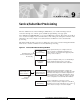
C H A P T E R 9 Service/Subscriber Provisioning The Cisco 6400 Service Connection Manager (SCM) allows you to make and manage network connections through a set of menu options available by right clicking on an appropriate Cisco 6400 Chassis, NSP, NRP, NLC, or port object in MapViewer window. These menu options allow you to create and configure services and subscribers, and to manage the subsequent connection of the subscribers to the services.
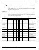
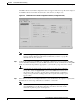
Chapter 9 Note Service/Subscriber Provisioning Each of the windows that appear in this chapter are described in greater detail in Chapter 10, “Service/Subscriber Provisioning Windows: Detailed Description”. See the “SCM Tasks” section on page 9-2 for details of the SCM tasks that you can execute and the objects that you select to begin the task. SCM Tasks Table 9-1 This section describes the tasks that you execute from each object type using the Cisco 6400 SCM Manager (c6400Manager) view.
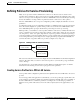
Chapter 9 Service/Subscriber Provisioning Defining Policies For Service Provisioning Defining Policies For Service Provisioning Many service providers and telecommunications carriers now offer tiered service levels to their customers and/or subscribers. These service levels are generally defined by the marketing policy of the carrier or service provider.
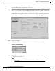
Chapter 9 Service/Subscriber Provisioning Defining Policies For Service Provisioning To create a PPPoA-SD service profile, follow these steps: Step 1 Select the Cisco 6400 UAC, Profiles, Configure PPPoA-SD Service Profiles option from a Site, Shelf, Chassis, or service instance object in the MapViewer window. Profiles are “globally” available within the Cisco 6400 SCM. The PPPoA-SD Service Profile Configuration window appears with the Configuration tab displayed.
Chapter 9 Service/Subscriber Provisioning Defining Policies For Service Provisioning The PPPoA-SD Service Profile Configuration window reappears with the new profile name displayed in the PPPoA-SD Service Profiles list at left side of the window (see Figure 9-5). Figure 9-5 Note Step 4 Select the Copy and Copy Page Configuration options in the Edit menu to cut and paste between different profiles. This is useful when you wish to copy profile information from one to the next.
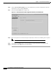
Chapter 9 Service/Subscriber Provisioning Defining Policies For Service Provisioning Step 6 Select a Subscriber Encapsulation type in the VC Parameters panel. The VC Parameters define the characteristics of the incoming ATM traffic. Step 7 Select the Service Details tab (see Figure 9-6). Figure 9-6 Step 8 PPPoA-SD Service Profile Configuration Window (Service Details Tab) Enter a description into the Service Description data entry box in the Service Details panel, if required.
Chapter 9 Service/Subscriber Provisioning Defining Policies For Service Provisioning Editing an Existing PPPoA-SD Service Profile To edit an existing PPPoA-SD service profile, follow these steps: Step 1 Select the Cisco 6400 UAC, Profiles, Configure PPPoA-SD Service Profiles option from a Site, Shelf, Chassis, or service instance object in the MapViewer window. The PPPoA-SD Service Profile Configuration window appears with the PPPoA-SD Configuration tab displayed.
Chapter 9 Service/Subscriber Provisioning Defining Policies For Service Provisioning Deleting an Existing PPPoA-SD Service Profile To delete an existing PPPoA service profile, follow these steps: Step 1 Select the Cisco 6400 UAC, Profiles, Configure PPPoA-SD Service Profiles option from a Site, Shelf, Chassis, or service instance object in the MapViewer window. The PPPoA-SD Service Profile Configuration window appears.
Chapter 9 Service/Subscriber Provisioning Defining Policies For Service Provisioning Creating Service Profiles for an L2TP Service L2TP service profiles define the configuration parameters for the uplink from the Cisco 6400 UAC to the service provider. You can set up profiles and apply them to the relevant NRP or, alternatively, you can set up and apply a profile with some of the parameters set and then configure the remaining parameters manually.
Chapter 9 Service/Subscriber Provisioning Defining Policies For Service Provisioning Note Each service profile must have a unique name. Do not insert spaces into a service profile name. The L2TP Service Profile Configuration window reappears with the name of the new profile displayed in the L2TP Service Profiles list at left side of the window. See the “L2TP Service Profile Configuration Window” section on page 10-4 for details of the parameters displayed.
Chapter 9 Service/Subscriber Provisioning Defining Policies For Service Provisioning Step 5 Select the Service Details tab. 41560 Figure 9-13 L2TP Service Profile Configuration Window (Service Details Tab) Step 6 Enter a description into the Service Description data entry box in the Service Details panel, when required. Entering a Service Description is optional. Step 7 Select the QoS Parameters tab.
Chapter 9 Service/Subscriber Provisioning Defining Policies For Service Provisioning Editing an Existing L2TP Service Profile To edit an existing L2TP service profile, follow these steps: Step 1 Select the Cisco 6400 UAC, Profiles, Configure L2TP Service Profiles option from a Site, Shelf, Chassis, or service instance object in the MapViewer window. The L2TP Service Profile Configuration window appears with the L2TP Configuration tab displayed.
Chapter 9 Service/Subscriber Provisioning Defining Policies For Service Provisioning Deleting an Existing L2TP Service Profile To delete an existing L2TP service profile, follow these steps: Step 1 Select the Cisco 6400 UAC, Profiles, Configure L2TP Service Profiles option from a Site, Shelf, Chassis, or service instance object in the MapViewer window. The L2TP Service Profile Configuration window appears.
Chapter 9 Service/Subscriber Provisioning Defining Policies For Service Provisioning Creating Service Profiles for an RFC1483 Bridging Service Service profiles define configuration parameters for the uplink from the Cisco 6400 UAC to the service provider. You can set up profiles and apply them or, alternatively, you can set up and apply a profile with some of the parameters set and then configure the remaining parameters manually.
Chapter 9 Service/Subscriber Provisioning Defining Policies For Service Provisioning Step 3 Note Step 4 Enter a name for the profile in the Enter profile name data entry box. Each service profile must have a unique name. Do not insert spaces into a service profile name. BR1483 Bridging Bronze was entered in the example shown in Figure 9-19. The new profile name appears in the BB Service Profiles list at left side of the window (see Figure 9-20).
Chapter 9 Service/Subscriber Provisioning Defining Policies For Service Provisioning Step 6 Select the Service Details tab (see Figure Figure 9-21). Figure 9-21 RFC1483 Bridging Service Profile Configuration Window (Service Details Tab) Step 7 Enter a description into the Service Description data entry box in the Service details panel, if required. Entering a Service Description is optional.
Chapter 9 Service/Subscriber Provisioning Defining Policies For Service Provisioning Step 8 Select the QoS Parameters tab (see Figure 9-22). Figure 9-22 RFC1483 Bridging Service Profile Configuration Window (QoS Parameters Tab) Step 9 Configure the parameters displayed in the QoS Parameters tab, as required. Step 10 Select Save from the File menu to save the parameters you have selected for your service profile. Step 11 Select Close from the File menu to close the window.
Chapter 9 Service/Subscriber Provisioning Defining Policies For Service Provisioning Editing an Existing RFC1483 Bridging Service Profile To edit an existing RFC1483 Bridging service profile, follow these steps: Step 1 Select the Cisco 6400 UAC, Profiles, Configure RFC1483 Bridging Service Profiles option from a Site, Shelf, Chassis, or service instance object in the MapViewer window. The RFC1483 Bridging Service Profile Configuration window appears with the Service Details tab displayed.
Chapter 9 Service/Subscriber Provisioning Defining Policies For Service Provisioning Deleting an Existing RFC1483 Bridging Service Profile To delete an existing RFC1483 Bridging service profile, follow these steps: Step 1 Select the Cisco 6400 UAC, Profiles, Configure RFC1483 Bridging Service Profiles option from a Site, Shelf, Chassis, or service instance object in the MapViewer window. The RFC1483 Bridging Service Profile Configuration window appears.
Chapter 9 Service/Subscriber Provisioning Defining Policies For Service Provisioning Creating Service Profiles for an RFC1483 IRB Service Service profiles define configuration parameters for the uplink from the Cisco 6400 UAC to the service provider. You can set up profiles and apply them or, alternatively, you can set up and apply a profile with some of the parameters set and then configure the remaining parameters manually.
Chapter 9 Service/Subscriber Provisioning Defining Policies For Service Provisioning Step 3 Enter a name for the profile in the Enter profile name data entry box. Premium Profile was entered in the example shown in Figure 9-27. Note Each service profile must have a unique name. Do not insert spaces into a service profile name. The new profile name displays in the BR Service Profiles list at left side of the window (see Figure 9-28).
Chapter 9 Service/Subscriber Provisioning Defining Policies For Service Provisioning Step 5 Select the Service Details tab (see Figure 9-29). Figure 9-29 RFC1483 IRB Service Profile Configuration Window (Service Details Tab) Step 6 Enter a description into the Service Description data entry box in the Service Details panel, as required. Entering a Service description is optional. Step 7 Select the QoS Parameters tab.
Chapter 9 Service/Subscriber Provisioning Defining Policies For Service Provisioning Step 8 Configure the parameters displayed in the QoS Parameters tab as required. Step 9 Select Save from the File menu to save the parameters you have selected for your service profile. Step 10 Select Close from the File menu to close the window.
Chapter 9 Service/Subscriber Provisioning Defining Policies For Service Provisioning Deleting an Existing RFC1483 IRB Service Profile To delete an existing IRB service profile, follow these steps: Step 1 Select the Cisco 6400 UAC, Profiles, Configure RFC1483 IRB Service Profiles option from a Site, Shelf, Chassis, or service instance object in the MapViewer window. The RFC1483 IRB Service Profile Configuration window appears.
Chapter 9 Service/Subscriber Provisioning Defining Policies For Service Provisioning Creating Service Profiles for an IP Uplink (for PTA-MD and RBE Subscribers) Service Service profiles define configuration parameters for the uplink from the Cisco 6400 UAC to the service provider. You can set up profiles and apply them or, alternatively, you can set up and apply a profile with some of the parameters set and then configure the remaining parameters manually.
Chapter 9 Service/Subscriber Provisioning Defining Policies For Service Provisioning Step 2 Select Create Profile. A Prompt window appears (see Figure 9-35). Figure 9-35 Prompt Window Step 3 Enter a name for the profile in the Enter profile name data entry box. IP Uplink Bronze was entered in the example shown in Figure 9-35. Note Each service profile must have a unique name. Do not insert spaces into a service profile name.
Chapter 9 Service/Subscriber Provisioning Defining Policies For Service Provisioning Step 5 Note You can apply an existing profile to a new profile to save time when configuring new profiles. Select the Apply Profile option from the Edit menu and then select the existing profile you wish to apply from the profiles listed. The configuration settings are copied from the existing profile to the new profile. The settings copied appear in blue.
Chapter 9 Service/Subscriber Provisioning Defining Policies For Service Provisioning Step 6 Configure the General, DNS Redirection / Fault Tolerance, and the Remote RADIUS Configuration parameters. Step 7 Select the QoS Parameters tab. Figure 9-38 IP Uplink Service Profile Configuration Window (QoS Parameters Tab) Step 8 Configure the Quality of Service (Receive) and Quality of Service (Transmit) parameters, as required.
Chapter 9 Service/Subscriber Provisioning Defining Policies For Service Provisioning Editing an Existing IP Uplink Service Profile To edit an existing IP Uplink service profile, follow these steps: Step 1 Select the Cisco 6400 UAC, Profiles, Configure IP Uplink Profiles option from a Site, Shelf, Chassis, or service instance object in the Map Viewer window. The IP Uplink Service Profile Configuration window appears with the Configuration tab displayed (see Figure 9-39).
Chapter 9 Service/Subscriber Provisioning Defining Policies For Service Provisioning Deleting an Existing IP Uplink Service Profile To delete an existing IP Uplink service profile, follow these steps: Step 1 Select the Cisco 6400 UAC, Profiles, Configure IP Uplink Profiles option from a Site, Shelf, Chassis, or service instance object in the Map Viewer window. The IP Uplink Service Configuration Profile window appears.
Chapter 9 Service/Subscriber Provisioning Defining Policies For Service Provisioning Connection Templates Connection Templates are very similar to VC Classes in Cisco IOS. The main difference is that, where a VC class is local to a specific NRP, Connection Templates are available for each Cisco 6400 UAC managed by the Cisco 6400 SCM application. When a parameter in a connection template is altered and applied, this change applies to all connections that use the template.
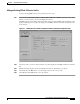
Chapter 9 Service/Subscriber Provisioning Defining Policies For Service Provisioning Figure 9-43 Deployment Wizard - Object Parameters Window 41501 Enter the number of Connection Template objects to create Step 4 Enter the Number of Connection Template objects you wish to deploy. Step 5 Click Forward. Step 6 Enter a name for the new Connection Template in the Object Parameters panel.
Chapter 9 Service/Subscriber Provisioning Defining Policies For Service Provisioning Step 7 Click Forward. Step 8 Repeat steps 6 and 7 for the Number of Connection Template objects entered in step 4. Step 9 The Deployment Summary details appear in the Deployment Wizard - Summary window (see Figure 9-45). Figure 9-45 Deployment Wizard - Summary Window 41503 Check the Deployment Summary information is correct Step 10 Check the summary information displayed is correct.
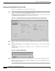
Chapter 9 Service/Subscriber Provisioning Defining Policies For Service Provisioning Step 3 Select the Cisco 6400 UAC, Connection, Connection Template Configuration option. The Connection Template Configuration window (see Figure 9-46) appears. 35329 Figure 9-46 Connection Template Configuration Window (QoS Parameters Tab) Step 4 Select a connection template from the Connection Template list displayed.
Chapter 9 Service/Subscriber Provisioning Service Provisioning Deleting Connection Templates Note Before deleting a connection template you must disconnect any subscribers connected to a service instance using that connection template. To delete connection templates, follow these steps: Step 1 Place the cursor over a relevant object in the a network map, a relevant object in the map view, or an object pick list on an open Element Manager window.
Chapter 9 Service/Subscriber Provisioning Service Provisioning Figure 9-47 Setting Up Services on the Cisco 6400 UAC Apply an existing Service Profile to a Service Instance All three steps are accomplished within the Service Configuration window appropriate for the selected service Configure an Appropriate Service Instance Commission the Service Instance Note A Service Instance holds all of the information related to that service.
Chapter 9 Service/Subscriber Provisioning Service Provisioning The Deployment Wizard Object Parameters (1 of 2) window appears (see Figure 9-48). Figure 9-48 Deployment Wizard - Object Parameters (1 of 2) Window 41524 Enter the number of service objects you wish to create Step 2 Enter the Number of Service objects to create. A single ATM Service object was entered in the example shown in Figure 9-48. Step 3 Select Forward.
Chapter 9 Service/Subscriber Provisioning Service Provisioning Figure 9-49 Deployment Wizard - Object Parameters (2 of 2) 41525 Enter the name for the service instance Step 4 Enter a Service Instance Name. ATM Service- One was entered in the example shown in Figure 9-49. Step 5 Select Forward. Note Repeat steps 4 and 5 for the Number of Service Instances entered in step 2, when required.
Chapter 9 Service/Subscriber Provisioning Service Provisioning Step 6 Click Forward. The Deployment Wizard Summary window appears (see Figure 9-50). Figure 9-50 Deployment Wizard - Summary 41526 The Summary panel displays information about the deployment Summary information displays in the Summary panel. Step 7 Check the Summary information is correct. Step 8 Click Finish (when the Deployment Summary information is correct) to create the new Service Instance objects.
Chapter 9 Service/Subscriber Provisioning Service Provisioning Configuring and Commissioning a Service Instance After you create the service instance object, you should configure and then commission the service instance from the appropriate Service Configuration window. The service instance object can be configured in two ways: • By applying an appropriate service profile and then manually configuring each of the remaining parameter in that service instance.
Chapter 9 Service/Subscriber Provisioning Service Provisioning Configuring and Commissioning a Pure ATM Service Instance To configure and commission a Pure ATM switching service instance, follow these steps: Step 1 Select the Cisco 6400 UAC, Service, Configure ATM Service option from the egress ATM line card object in MapViewer. Note You cannot apply a profile to the pure ATM switching service. The ATM Service Configuration window appears (see Figure 9-53).
Chapter 9 Service/Subscriber Provisioning Service Provisioning Figure 9-54 ATM Service Configuration Window (Service Uplink Tab) Step 7 Enter details into the parameters displayed in the Service Uplink PVC panel, as required. See the “Service Uplink Tab” section on page 10-25 for further details on the parameters displayed. Commissioning the Pure ATM Service Instance Note Step 8 This is the first stage at which you actually “roll” the selected service configuration onto the Cisco 6400 UAC hardware.
Chapter 9 Service/Subscriber Provisioning Service Provisioning Step 10 Check the details in the Action Report window to ensure that the service was commissioned successfully. Step 11 Select Save to save the Action Report, if required. Step 12 Select Close to close the Action Report window and return to the Service Instance Configuration window. Step 13 Select Close from the File menu to close the Service Instance Configuration window.
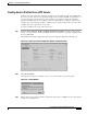
Chapter 9 Service/Subscriber Provisioning Service Provisioning Configuration window. The PPPoA-SD Services list is empty when no PPPoA-SD instances have been created. See the “Creating a Service Instance” section on page 9-36 for details on how to create a service instance. Note Proceed to the “Configuring the PPPoA-SD Service Parameters” section on page 9-44 if you are not applying a service profile. Applying a PPPoA-SD Service Profile Step 3 Select Apply Profile from the Edit menu.
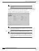
Chapter 9 Service/Subscriber Provisioning Service Provisioning Step 7 Enter a Service Description, if required. Step 8 Select a connection from the Current Connection list and configure the values in the Subscriber Connections panel, as required. Commissioning the PPPoA-SD Service Step 9 Click Commission Service to roll the service onto the selected Cisco 6400 UAC. A pop up window appears for you to confirm that you wish to commission the selected service.
Chapter 9 Service/Subscriber Provisioning Service Provisioning Caution The Cisco 6400 SCM will roll-back configuration changes applied if an error is detected in the execution of the Cisco IOS command sequence with your selected parameters. This insures that the Cisco 6400 UAC remains in a consistent state, even when errors are made entering parameters. Step 12 Select Save to save the Action Report, if required.
Chapter 9 Service/Subscriber Provisioning Service Provisioning Now create the required entries in the IP Routing Table: NRP(config)#ip route 255.255.255.255 atm0/0/0. where, is as configured previously is as configured previously.
Chapter 9 Service/Subscriber Provisioning Service Provisioning Applying an L2TP Service Profile Step 3 Select Apply Profile from the Edit menu. Step 4 Select the appropriate profile from the list of profiles displayed. The profile parameters are copied to the appropriate service instance parameters in the L2TP Service Configuration window and appear in blue. Configuring the L2TP Service Parameters Step 5 Configure the parameters displayed on the Configuration tab, as required.
Chapter 9 Service/Subscriber Provisioning Service Provisioning 41557 Figure 9-62 L2TP Service Configuration Window (Service Uplink Tab) See the “Service Uplink Tab” section on page 10-32 for further details on the parameters displayed. Step 11 Configure the parameters displayed in the Service Uplink PCV, Quality of Service (Receive), Internal NSP, NRP PVC and Quality of Service (Transmit), as required.
Chapter 9 Service/Subscriber Provisioning Service Provisioning Figure 9-64 Action Report Window The Action Report window details the Cisco IOS commands executed when the service is commissioned. Invalid Cisco IOS commands result in a failure to commission the service. Step 14 Caution Check the details in the Action Report window to ensure that the service was commissioned successfully.
Chapter 9 Service/Subscriber Provisioning Service Provisioning Configuring and Commissioning an RFC1483 Bridging Service Instance To configure and commission an RFC1483 Bridging service instance, follow these steps: Step 1 Select the Cisco 6400 UAC, Service, Configure RFC1483 Bridging Service option from a Site, Shelf, Chassis, or service instance object.
Chapter 9 Service/Subscriber Provisioning Service Provisioning Applying a RFC1483 Bridging Service Profile Step 3 Select Apply Profile from the Edit menu. Step 4 Select the appropriate profile from the list of profiles displayed. The profile parameters are copied to the appropriate service instance parameters in the RFC1483 Bridging Service Configuration window and appear in blue.
Chapter 9 Service/Subscriber Provisioning Service Provisioning Step 10 Configure the parameters displayed in the Subscriber Connections panel. Step 11 Select the Service Uplink tab. Figure 9-67 RFC1483 Bridging Service Configuration Window (Service Uplink Tab) See the “Service Uplink Tab” section on page 10-37 for further details on the parameters displayed.
Chapter 9 Service/Subscriber Provisioning Service Provisioning Step 14 Select Yes to commission the service (or No to return to the RFC1483 Bridging Service Configuration window). The Action Report window appears. Figure 9-69 Action Report Window The Action Report window details the Cisco IOS commands executed when the service is commissioned. Invalid Cisco IOS commands result in a failure to commission the service.
Chapter 9 Service/Subscriber Provisioning Service Provisioning Configuring and Commissioning a RFC1483 IRB Service Instance To configure and commission an RFC1483 IRB service instance, follow these steps: Step 1 Select the Cisco 6400 UAC, Service, Configure RFC1483 IRB Service option from a Site, Shelf, Chassis, or service instance object. The RFC1483 IRB Service Configuration window appears.
Chapter 9 Service/Subscriber Provisioning Service Provisioning Applying a RFC1483 IRB Service Profile Step 3 Select Apply Profile from the Edit menu. Step 4 Select the appropriate profile from the list of profiles displayed. The profile parameters are copied to the appropriate service instance parameters in the RFC1483 IRB Service Configuration window and appear in blue. Configuring the RFC1483 IRB Service Parameters Step 5 Configure the parameters displayed on the Configuration tab, as required.
Chapter 9 Service/Subscriber Provisioning Service Provisioning Step 10 Select the Service Uplink tab. Figure 9-72 RFC1483 IRB Service Configuration Window (Service Uplink Tab) See the “Service Uplink Tab” section on page 10-43 for details on the parameters displayed on the Service Uplink tab. Step 11 Configure the parameters displayed on the Service Uplink tab, as required. Commissioning the RFC1483 IRB Service Step 12 Click Commission Service to roll the service onto the Cisco 6400 UAC.
Chapter 9 Service/Subscriber Provisioning Service Provisioning Step 13 Select Yes to commission the service (or No to return to the RFC1483 IRB Service Configuration window). The Action Report window appears. Figure 9-74 Action Report Window The Action Report window details the Cisco IOS commands executed when the service is commissioned. Invalid Cisco IOS commands result in a failure to commission the service.
Chapter 9 Service/Subscriber Provisioning Service Provisioning Configuring and Commissioning an IP Uplink (for PTA-MD and RBE Subscribers) Service Instance To configure and commission an IP Uplink service instance, follow these steps: Step 1 Select the Cisco 6400 UAC, Service, Configure IP Uplink Service option from a Site, Shelf, Chassis, or service instance object. The IP Uplink Service Configuration window appears (see Figure 9-75).
Chapter 9 Service/Subscriber Provisioning Service Provisioning Applying a IP Uplink (for PTA-MD and RBE Subscribers) Service Profile Step 3 Select Apply Profile from the Edit menu. Step 4 Select the appropriate profile from the list of profiles displayed. The profile parameters are copied to the appropriate service instance parameters in the IP Uplink Service Configuration window and appear in blue.
Chapter 9 Service/Subscriber Provisioning Service Provisioning Step 8 Select the Service Uplink tab. Figure 9-77 IP Uplink Service Configuration Window (Service Uplink Tab) See the “Service Uplink Tab” section on page 10-50 for further details on the parameters displayed. Step 9 Configure the parameters displayed on the Service Uplink tab, as required. Commissioning the IP Uplink (for PTA-MD and RBE Subscribers) Service Step 10 Click Commission Service to roll the service onto the Cisco 6400 UAC.
Chapter 9 Service/Subscriber Provisioning Service Provisioning Step 11 Select Yes to commission the service (or No to return to the IP Uplink Service Configuration window). The Action Report window appears. Figure 9-79 Action Report Window The Action Report window details the Cisco IOS commands executed when the service is commissioned. Invalid Cisco IOS commands result in a failure to commission the service.
Chapter 9 Service/Subscriber Provisioning Service Provisioning Configuring and Commissioning an RFC1483 Routing Service Instance To configure and commission an RFC1483 routing service instance, follow these steps: Step 1 Select the Cisco 6400 UAC, Service, Configure RFC1483 Routing Services option from a Site, Shelf, Chassis, or service instance object. The RFC1483 Routing Service Configuration window appears (see Figure 9-80).
Chapter 9 Service/Subscriber Provisioning Service Provisioning Step 4 Select the Service Details tab. Figure 9-81 RFC1483 Routing Service Configuration Window (Service Details Tab) Step 5 Enter a Service Description in the Service Details panel, when required. Step 6 Select a connection from the Current Connection list and configure the parameters in the Subscriber Connections panel, as required. Step 7 Select the Service Uplink tab.
Chapter 9 Service/Subscriber Provisioning Service Provisioning Figure 9-82 RFC1483 Routing Service Configuration Window (Service Uplink Tab) See the “RFC1483 Routing Service Configuration Window” section on page 10-52 for further details on the parameters displayed. Step 8 Configure the parameters displayed on the Service Uplink tab, as required. Step 9 Click Add to add a new service uplink. The RFC1483 services can have multiple service uplinks.
Chapter 9 Service/Subscriber Provisioning Service Provisioning Step 11 Select Yes to commission the service (or No to return to the RFC1483 Routing Service Configuration window). The Action Report window appears. Figure 9-84 Action Report Window The Action Report window details the Cisco IOS commands executed when the service is commissioned. Invalid Cisco IOS commands result in a failure to commission the service.
Chapter 9 Service/Subscriber Provisioning Subscriber Provisioning Subscriber Provisioning Figure 9-85 displays a typical work flow that describes how to create, configure and connect subscribers (that is, provision end customers).
Chapter 9 Service/Subscriber Provisioning Subscriber Provisioning Step 1 Select the Cisco 6400 UAC, Subscriber, Deploy option from a Line Card. The Deployment Wizard Object Parameters window (1 of 2) appears. (see Figure 9-86) Figure 9-86 Deployment Wizard - Object Parameters (1 of 2) 41529 Enter the number of Subscriber objects to create Step 2 Enter the Number of Subscriber objects you wish to create. A single Subscriber object was entered in the example.
Chapter 9 Service/Subscriber Provisioning Subscriber Provisioning Step 3 Select Forward. The Deployment Wizard - Object Parameters (2 of 2) window appears. (see Figure 9-87) Figure 9-87 Deployment Wizard - Object Parameters (2 of 2) 41530 Enter the Subscriber's ID Step 4 Enter a Subscriber ID. John Smith was entered in the example. (see Figure 9-87) Step 5 Click Forward. Note Repeat steps 4 and 5 for the Number of Subscribers entered in step 2.
Chapter 9 Service/Subscriber Provisioning Subscriber Provisioning Step 6 Click Forward. The Deployment Wizard Summary window appears (see Figure 9-88). Figure 9-88 Deployment Wizard - Summary 41531 The Summary panel displays information about the deployment Summary information displays in the Summary panel. Step 7 Check the Summary information is correct. Step 8 Click Finish (when the Deployment Summary information is correct) to create the new Subscriber objects.
Chapter 9 Service/Subscriber Provisioning Subscriber Provisioning Configuring a Subscriber To configure a subscriber’s details, follow these steps: Step 1 Select the Cisco 6400 UAC, Subscriber, Configure Subscriber option at an appropriate Line Card. The Subscriber Configuration window appears (see Figure 9-89).
Chapter 9 Service/Subscriber Provisioning Subscriber Provisioning Step 5 Select the Subscriber Details (Optional) tab. Figure 9-90 Subscriber Configuration Window (Subscriber Details (Optional) Tab) Note Entering information into the Subscriber Details (Optional) tab is voluntary. You can enter any information you like into the Subscriber Details tab. For example, you may decide to enter a subscriber identification in the Subscriber Name box and an e-mail address in the Subscriber Address box.
Chapter 9 Service/Subscriber Provisioning Subscriber Provisioning Table 9-2 displays the Cisco 6400 SCM service types and the tabs in the Service/Subscriber Connection window that should be configured for each service type.
Chapter 9 Service/Subscriber Provisioning Subscriber Provisioning Figure 9-91 Service/Subscriber Connection Window (Connection Details Tab) Step 2 Select a Cisco 6400 chassis from the Cisco 6400 list displayed on the left side of the window. Step 3 Select a Subscriber from the Subscriber list displayed on the left side of the window. Step 4 Select a Connection Template from the Connection Template list displayed on the left side of the window.
Chapter 9 Service/Subscriber Provisioning Subscriber Provisioning Step 6 Select the Connect to Single Domain tab. Note When you select an IP Uplink service (Service Type of PTA-MD) and this service instance does not have a Local Service Profile (LSP) configured, the Connect button is grayed out. When you do connect to an IP Uplink service using the Connect to Single Domain tab, this is equivalent to the PTA-MD static case used in Release 1.3 of the Cisco 6400 SCM software.
Chapter 9 Service/Subscriber Provisioning Subscriber Provisioning Step 8 Configure the parameters displayed in the Connect to Single Domain tab, as required. Step 9 Select the Connect to Multi-Domain tab. Figure 9-93 Service/Subscriber Connection Window (Connect to Multi-Domain Tab) Step 10 Select an NRP from the Node Route Processor list. Step 11 Configure the parameters displayed in the Connect to Multi-Domain tab, as required. Step 12 Click Connect.
Chapter 9 Service/Subscriber Provisioning Subscriber Provisioning Note A Subscriber connection object is automatically created and placed below the appropriate service instance in the Cisco6400ServiceView and also in the Cisco6400SubscriberView below the appropriate subscriber object. Performance logging can be Activated or Deactivated for each subscriber connection object. See Table 8-1 on page 8-2 for further details.
Chapter 9 Service/Subscriber Provisioning Subscriber Provisioning Disconnecting a Subscriber from a Service Instance To disconnect a subscriber from a service instance, follow these steps: Step 1 Select the Cisco 6400 UAC, Subscriber, Disconnect s option from an NSP card. The Service/Subscriber Disconnection window appears.
Chapter 9 Service/Subscriber Provisioning Subscriber Provisioning Step 5 Click Yes to disconnect the subscriber. The Action Report window appears confirming that the subscriber was disconnected. Figure 9-97 Action Report Window Step 6 Click Close to close the Action Report window or click Save to save the Action Report. The Action Report can be saved and used for diagnostic purposes. The “*** No errors encountered *** ” message appears to show that disconnection was successful.
Chapter 9 Service/Subscriber Provisioning Administration Administration Editing a Currently Connected Subscriber’s Details This operation can be performed without disconnecting the subscriber. To edit a currently connected subscriber’s details, follow these steps: Step 1 Select the Configure Subscribers option from a line card. Step 2 Select the NSP, DSLAM and Subscriber to display the subscribers details. Step 3 Enter the Contact and Subscriber Details and then save your changes.