Cisco SFS Multifabric Server Switch Shelf & Rack Ear Kit Installation Guide (Topspin 360) Part Number: OL-7733-01 Product ID: 140273
Copyright © 2004 - 2005 Topspin Communications, Inc. All rights reserved. The Topspin Switched Computing System, Topspin Host Channel Adapter, Topspin Element Manager, and collateral software programs and documentation are subject to and made available only pursuant to the license agreement signed by you and Topspin, Communications, Inc. (or if no signed license agreement exists, the license agreement included with your original media) and may only be used in accordance with the terms of that agreement.
1 1 Topspin Shelf and Rack Ear Kit Contents The following contents are included in this package: ______ Topspin Shelf and Rack Ear Kit for Topspin 360 Contents and Installation Guide(1) ______ Shelf (1) ______ Rack Ears (2) ______ Flat Countersink Screws (8) ______ Panhead Screws (4) To register your products with Topspin customer support, or to locate more detailed hardware information: http://www.topspin.
2
3 2 Rack the Topspin 360 with the Optional Topspin Shelf and Rack Ear Kit The Topspin 360 can be installed using your own rack shelf. Refer to the Topspin 360 Hardware Guide for instructions on racking the server switch without the optional Topspin shelf. This document describes the installation of the Topspin 360 server switches if you have purchased the optional shelf kit.
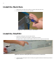
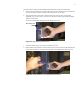
4 Install the Rack Ears 1. Determine the end of the Server Switch to position at the front of the rack. 2. Install the rack ears using the screws provided. Figure 2-1: Install the Rack Ears on the Chassis Install the Shelf Kit 1. Separate the sliding piece from the main shelf unit. Note the way that the pieces fit together. The flanges face outward. The right bracket is engraved with an EXR, and the left bracket is engraved with an EXL.
5 The right bracket is engraved with an EXR, and the left bracket is engraved with an EXL. a. Set one of the wide bracket pieces against the inside of the rack. The flange of the bracket faces outward, and wraps around to rest against the outside of the rear rack post. b. Align the holes of the bracket piece with the holes of the rack post. This varies slightly depending on your rack; however, in most cases, the bottom of the bracket should be aligned with the 1U hash mark.
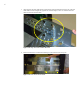
6 3. Align the back end of the shelf with the exposed ends of the mounted brackets in the rack. The back of the shelf unit is the straight end (opposite the end with flanges). There are channels inside the shelf into which the brackets slide. Figure 2-5: Align Shelf with Installed Brackets 4. Push the shelf into the rack until the front flanges of the shelf meets the rack posts.
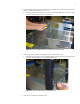
7 5. Screw the bracket and shelf together from the inside (required). The number of screws that you use on each side will depend on the size of your rack. a. Depending on the amount collapse or extension required of the shelf to fit your rack, use either two screws (minimum) or four screws (maximum). Figure 2-7: Screw the Bracket Into the Shelf From Inside the Rack 6. Attach the front of the shelf to the rack posts, using screws that fit your rack. a.
8 Lift the Chassis onto the Shelf 8. Place the switch in the rack. a. Lift the switch (using at least two people). Face the side of the chassis without handles toward the rack. b. Rest the end of the chassis at the edge of the shelf. Push the chassis back into the rack until the handles meet the rack posts. Make sure that the left and right sides of the chassis are pushed back evenly. NOTE: There are no side rails for the current Topspin 360 chassis. Secure the Chassis 9.