TD 92322GB Installation and Operation Manual Integrated Message Server, IMS/IP-WiFi 2007-06-26/ Ver.
Installation and Operation Manual Integrated Message Server, IMS/IP-WiFi TD 92322GB Contents 1 Introduction............................................................................................................. 1 1.1 Requirements ..................................................................................................... 2 2 Installation (ELISE2)................................................................................................. 3 2.1 Description of LED Indications ............
Installation and Operation Manual Integrated Message Server, IMS/IP-WiFi TD 92322GB 7 IMS/IP Phonebook Configuration ........................................................................ 15 7.1 Technical Specification ..................................................................................... 15 7.2 Phonebook address .......................................................................................... 15 7.3 Phonebook Setup ................................................................
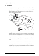
Installation and Operation Manual Integrated Message Server, IMS/IP-WiFi 1 TD 92322GB Introduction This document describes the installation and configuration of IMS/IP-WiFi, the Integrated Message Server for the VoWiFi system. The IMS/IP-WiFi is a message server based on the ELISE hardware. It acts as a messaging gateway and controls messaging and alarm between Ascom messaging systems and the VoWiFi handsets in the VoWiFi System.
Installation and Operation Manual Integrated Message Server, IMS/IP-WiFi 1.1 TD 92322GB Requirements • Microsoft Internet Explorer 6.
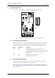
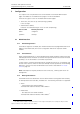
Installation and Operation Manual Integrated Message Server, IMS/IP-WiFi 2 TD 92322GB Installation (ELISE2) LED2 LED3 LED4 LED5 This chapter is a complement to Installation Guide, ELISE2, TD 92232GB. SW4 LED1 BAT1 1 SW3 8 LED5 LED2 1 SW2 8 J1 6 IC1 J2 J16 5 J22 1 IC24 1 J9 J10 J12 S3 6 J11 4 J6 1 2 J14 J15 LED6 LED7 J16 1 J4 J11 J8 J20 1 J5 4 1 J6 4 1 J12 J13 2 S4 1J242 S5 S1 S2 J14 013 J7 Figure 2.
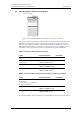
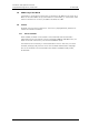
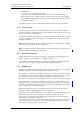
Installation and Operation Manual Integrated Message Server, IMS/IP-WiFi 2.3 TD 92322GB Function Indicator and Error Relay Output 003 Function indicator Figure 3. The function indicator that indicates the status of the IMS/IP The function indicator and the error relay indicate the status of the IMS/IP. The indication is dependent of whether the IMS/IP is connected to the A-bus or not, and also whether there is a Central Unit connected to the A-bus.
Installation and Operation Manual Integrated Message Server, IMS/IP-WiFi 2.4 TD 92322GB Addressing of the IMS/IP If the IMS/IP is connected to an A-bus with a Central Unit, the address must not be set to 00 nor to the same address as any other module. In other modes, i.e. connected to A-bus without Central Unit or no A-bus, the address should be set to 00. 2.5 Licence All IMS/IP units must have a valid licence. The licence is preprogrammed, and does not need to be entered at installation. 2.5.
Installation and Operation Manual Integrated Message Server, IMS/IP-WiFi 3 TD 92322GB Configuration This chapter covers the parameters that can be altered on the IMS/IP Administration pages. The address to the administration pages is xxx.xxx.xxx.xxx/admin. There are two types of users for the IMS/IP administration pages: • Technicians, first time set up commissioning (sysadmin) Full access right. • Administrators (admin) Limitation in troubleshooting (no access to view complete log). 3.
Installation and Operation Manual Integrated Message Server, IMS/IP-WiFi TD 92322GB • Availability Info - Change of status of the VoWiFi handsets. (The status can be changed from the IMS/IP GUI or from the VoWiFi handset). When an alarm or user key data message is received from a PP, the PP MAC address shall be added as extended information in the original sender (USD) when the message is distributed on UNITE. The addressing of the receivers is described in Installation Guide, ELISE2, TD 92232GB. 3.1.
Installation and Operation Manual Integrated Message Server, IMS/IP-WiFi TD 92322GB If individual passwords is needed, for example for shared phones, passwords can either be specified in a User Server or the individual call numbers can be used, refer to 3.1.2 Shared Phones. Forced login allows a user to login with a call number that already is in use. The handset that already is logged in will then be unregistered.
Installation and Operation Manual Integrated Message Server, IMS/IP-WiFi TD 92322GB bus, this parameter has to be set manually. See System Planning, On-site Paging System, TD 90202GB for more information. • Send module status from A-bus to Unite The IMS/IP can send module status received from the A-bus to the Unite system. This also means that if IMS/IP is connected as slave it will subscribe for module status from the central unit in system 900.
Installation and Operation Manual Integrated Message Server, IMS/IP-WiFi 3.3.3 TD 92322GB User Server IMS/IP can use an ESS as a user server for authentication of portables, see 3.1.6 WLAN System on page 7. 4 1 Select System Setup > User Server on the IMS/IP administration page. 2 Enter the IP address of the ESS which has users defined and click “Activate”.
Installation and Operation Manual Integrated Message Server, IMS/IP-WiFi 6 TD 92322GB Basic Alarm Manager A Basic Alarm Manager that can trigger on alarms and data sent from VoWiFi handsets are included in the IMS/IP. Activated inputs on the IMS/IP or a module on the A-bus can also be triggered. The Basic Alarm Manager can send messages to Pocket Units as a reaction to the incoming information. It is also possible to activate outputs on the IMS/IP or modules on the A-bus.
Installation and Operation Manual Integrated Message Server, IMS/IP-WiFi 6.1 6.2 6.3 TD 92322GB Nomenclature Input An input on the IMS/IP or an input on an Alarm Module connected to the Abus. Output An output on the IMS/IP or an output on an Output Module connected to the A-bus. Trigger A set of conditions that detects whether an input has been activated, or an alarm or data has been sent from a VoWiFi handset.
Installation and Operation Manual Integrated Message Server, IMS/IP-WiFi 3 TD 92322GB Enter the address 127.0.0.1/BAM in one address field. Click the “Activate” button. Configuration of Alarm and User Data 1 Open the IMS/IP administration pages and click “Message Distribution” for the WLAN Interface. 2 Click “Alarm”, see figure 6. Figure 6. Setting up the Message Distribution list for the WLAN Interface to send information to the Basic Alarm Manager. 6.4 3 Enter the address 127.0.0.
Installation and Operation Manual Integrated Message Server, IMS/IP-WiFi TD 92322GB IMS/IP outputs1 The IMS/IP has two outputs that can be used by the Basic Alarm Manager. These outputs are predefined in the Basic Alarm Manager at delivery. The initial state, i.e. high or low, for the output can also be set from the Basic Alarm Manager. Output Module outputs The number of outputs that can be used in the Basic Alarm Manager can be extended by using an Output Module connected to the A-bus.
Installation and Operation Manual Integrated Message Server, IMS/IP-WiFi 7 TD 92322GB IMS/IP Phonebook Configuration This chapter describes the configuration of the internal IMS/IP Phonebook. For information about installation and configuration of the Phonebook Service, see 10 Phonebook Service and Route2ELISE on page 25. The internal IMS/IP Phonebook gives the possibility to search for phone numbers in a local database or in an LDAP server.
Installation and Operation Manual Integrated Message Server, IMS/IP-WiFi 7.3 TD 92322GB Phonebook Setup Figure 1. Figure 7. IMS/IP Phonebook 7.3.1 Enter Search result texts When a request is sent to the phonebook, a text is included in the response that is sent to the handset. These texts can be customized, for example translated. 1 Open the IMS/IP administration pages and click “Phonebook”.
Installation and Operation Manual Integrated Message Server, IMS/IP-WiFi 7.4.1 TD 92322GB Update the Local Database The phonebook entries can be created from any CSV file and also from the web interface. Import a CSV file The CSV file can be created using Microsoft Excel or any leading spreadsheet or relational database, and should have the following format: First name 1;Family name 1;Phone number 1 First name 2;Family name 2;Phone number 2 The CSV file is imported as described below.
Installation and Operation Manual Integrated Message Server, IMS/IP-WiFi 7.4.2 TD 92322GB Export the Local Database The phonebook database can be exported to a CSV file for editing and backup reasons. 1 Open the page: http://xxx.xxx.xxx.xxx/user. Log on with user. The default password is password. 2 Click the Administrate IMS/IP Phonebook link. The window shown in figure 10 will appear. Figure 10. Exporting a CSV file. 3 7.4.3 Click “Export file”. Select “Save this file to disk”.
Installation and Operation Manual Integrated Message Server, IMS/IP-WiFi 7.5 TD 92322GB LDAP Parameter Setup The Lightweight Directory Access Protocol (LDAP) is an application protocol for querying and modifying directory services running over TCP/IP. The IMS/IP starts an LDAP session by connecting to an LDAP server. The IMS/IP then sends operation requests to the server, and the server sends responses in return.
Installation and Operation Manual Integrated Message Server, IMS/IP-WiFi 7.6 TD 92322GB Examples of Settings • LDAP directory in VoIP Gateway Figure 5. i Figure 11. Settings for the LDAP directory in the VoIP Gateway • Active directory 2003 Figure 6. Figure 12. Settings for Active directory 2003 • Cisco CallManager Figure 7. Figure 13. Settings for Cisco CallManager 2007-06-26/ Ver.
Installation and Operation Manual Integrated Message Server, IMS/IP-WiFi 7.7 TD 92322GB Operation The user accesses the phonebook by sending a message from the handset. The message includes a search query containing part of the first name and/or the family name, or phone number, see below.
Installation and Operation Manual Integrated Message Server, IMS/IP-WiFi 8 TD 92322GB Handset Administration Handset Administration gives the possibility to list all handsets that are registered in the system, search for a specific handset or a range of handsets 8.1 Search for Registered Handsets 1 Open the IMS/IP administration pages and click “Handset Administration” for the WLAN Interface. Figure 14. Handset Administration pages.
Installation and Operation Manual Integrated Message Server, IMS/IP-WiFi 8.1.2 TD 92322GB Remove IP Address, force a Relogin, or Delete a VoWiFi handset 1 Check the handset(s) checkbox in the search result list, see figure 15 on page 22 2 Click “Remove IP Address”, “Force Relogin” or “Delete Selected”. • Remove IP Address Can be used to reset the address of an handset. • Force Relogin Can be used to check the connection with a handset. • Delete Selected Can be used to remove numbers not in use. 8.1.
Installation and Operation Manual Integrated Message Server, IMS/IP-WiFi 9 TD 92322GB Messaging tool A web-based messaging tool that can be used to send messages to handsets is included in the IMS/IP. The tool is opened when the IP address or DNS name is entered in the browser’s address field, and can be used to send messages with predefined priority and beep characteristics to Pocket Units. The figure below describes how to use the messaging tool.
Installation and Operation Manual Integrated Message Server, IMS/IP-WiFi 10 TD 92322GB Phonebook Service and Route2ELISE A CD with Phonebook Service and Route2ELISE is included in the IMS/IP delivery. For more information about the Phonebook Service and how to install it, see documentation included on the CD and also Installation and Operation Manual, Phonebook Service. Route2ELISE is used during the installation. See Installation Guide, ELISE for more information.
Installation and Operation Manual Integrated Message Server, IMS/IP-WiFi 12 TD 92322GB Related Documents Data Sheet, Integrated Message Server IMS/IP - WiFi TD 92321GB Installation Guide, ELISE2 TD 92232GB Function Description, Open Access Protocol TD 92215GB Function Description, Activity Logging in Unite TD 92341GB Installation and Operation Manual, Phonebook Service TD 92360GB Installation and Operation Manual, Enhanced System Services, ESS TD 92253GB Installation Guide, T941AM8 Alarm Module
Installation and Operation Manual Integrated Message Server, IMS/IP-WiFi TD 92322GB Document History For details in the latest version, see change bars in the document. Version Date A 2006-02-13 First released version B 2006-03-06 Authentication information in 3.1.6 WLAN System on page 7, and new chapter 3.3.3 User Server on page 10. C 2007-02-14 New chapter 3.1.2 Shared Phones on page 6.
Installation and Operation Manual Integrated Message Server, IMS/IP-WiFi TD 92322GB Appendix A: IMS/IP and Firewalls If an application or unit has to communicate through a firewall with the IMS/IP, communication has to be permitted on the ports that are used.
Installation and Operation Manual Integrated Message Server, IMS/IP-WiFi TD 92322GB Appendix B: Basic Alarm Manager Configuration Examples System Components 1 Alarm Module, 1 inputs has been defined in the Basic Alarm Manager. Input names: Cold-storage room 1 1 Output Module, 2 outputs have been defined in the Basic Alarm Manager. Output names: Lamp cold-storage 1, Siren 4 Handsets with push-button, no-movement, man-down, and pull-cord alarms.
Installation and Operation Manual Integrated Message Server, IMS/IP-WiFi TD 92322GB Activate Output Action Output Activation Duration Siren Low – The output is set to the initial state again. Example 2 When the door to one of the cold-storage rooms is opened, the input “Cold-storage room 1” is closed. If the door is open longer than 2 minutes a message is sent and lamp above the door is lit. Another message is sent after 10 minutes if the door still is open.
Installation and Operation Manual Integrated Message Server, IMS/IP-WiFi TD 92322GB Send Message Actions Handset Address Message text Beep code 1440 Cold-storage room 1, door still open 4 Cold-storage room 1, door open very long Input Trigger Input Activation Activation Repetition Max. No. of time (s) time (s) Repetitions Cold-storage room 1 Close 1800 – 100 When the door has been open for 30 minutes (1800 seconds), the message is sent to all handsets and the siren starts to sound.