
User manual

Replacing the Chassis Fan Assembly
Book Title
4-20
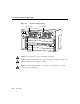
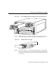
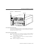
Step 4 Verify that the green LED on the power supply front panel is on (see
Figure 4-8). This indicates that the power supply is on and is receiving DC
source power, providing +5, +12, and +24 VDC to internal components, and
ensuring that all internal voltages are within tolerance.
Step 5 Verify that the appropriate ATM switch processor PS0 and PS1 LEDs are on and
are green (see Figure 4-2).
Step 6 Use the show environment command to display the power supply and system
status, as in the following screen example:
Switch# show environment
Temperature: OK
Fan: OK
Voltage: OK
Power Supply#0 type: Astec, status: OK
Power Supply#1 type: Astec, status: OK
Switch#
If the LEDs or show environment command indicate a power problem or other
system problem, refer to the section “Confirming the Installation” in the chapter
“Installing the LightStream 1010 ATM Switch Chassis” and Figure 2-11 for
troubleshooting information.
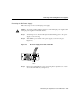
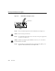
Replacing the Chassis Fan Assembly
This section describes how to replace the fan assembly (the chassis fans in a single unit that
draw in cooling air and distribute it across the ASP, CMs, and PAMs).
Note Each replaceable component ships with installation instructions. Refer to these
instructions for updated procedures and information.
Caution Before performing any procedures in this chapter, review the sections “Safety
Recommendations,” “Ensuring Safety with Electricity,” and “Preventing Electrostatic
Discharge Damage” in the chapter “Installing the LightStream 1010 ATM Switch Chassis.”