C H A PT E R 4 Maintaining the LightStream 1010 ATM Switch This chapter describes maintenance procedures for adding and replacing internal system components such as the system fan assembly and power supplies for the LightStream 1010 ATM switch. Your switch is configured as specified in your order and is ready for installation and startup when it leaves the factory. As your communication requirements change, you can upgrade your system, add components, or change the initial configuration.
Removing and Installing the ASP, CMs, and PAMs Removing and Installing the ASP, CMs, and PAMs All CMs and PAMs support hot swapping, which allows you to remove, install, and rearrange the CMs or PAMs without turning off the system power. When the system detects that a CM or PAM has been installed or removed, it automatically runs diagnostic and discovery routines, acknowledges the presence or absence of the PAM, and resumes system operation without any operator intervention.
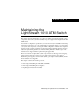
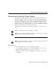
Power Supply LEDs If the source power or any of the internal DC voltages exceed allowable tolerances, the LED goes off and the system environmental monitor messages indicate the out-of-tolerance line. Because the system requires all three output voltages for operation, the system malfunctions or shuts down if any of the internal DC voltages reach an out-of-tolerance state. Figure 4-1 Power Supply LED (AC Power Supply Shown) LED H5588 Power 100-127/200-240V~ 8.0/4.
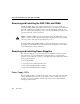
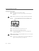
Removing and Installing Power Supplies ATM Switch Processor Power Supply LEDs N US T TA S FA T SE RE 1 PS TX RX K 0 LIN PS et En H8638 Figure 4-2 1 PS 0 PS Table 4-1 Power supply status LEDs ATM Switch Processor Power Supply LEDs LED Description PS0 If the left bay power supply is operational, the PS0 LED is green. If the left bay power supply is turned off or is not operational, the PS0 LED is red. If the left bay power supply is not installed, the PS0 LED is off.
Removing and Installing AC Power Supplies Removing and Installing AC Power Supplies The 376W power supplies (AC-input) support redundant hot swapping. When two power supplies are installed, you can remove or install one of the supplies without affecting system operation. When power is removed from one supply, the redundant power feature causes the second supply to ramp up to full power and maintain uninterrupted system operation.
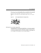
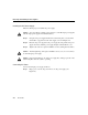
Removing and Installing Power Supplies Removing AC Power Supplies Take the following steps to remove an AC power supply: Step 1 Turn OFF the power switch on the power supply you are removing. (See Figure 4-3.) Caution Failure to turn off the AC power supply could result in equipment damage. Figure 4-3 AC Power Supply Switch, AC Connection, and Captive Screws Captive screws LED H9795 Power 100-127/200-240V~ 8.0/4.
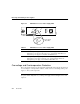
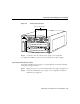
Removing and Installing AC Power Supplies Figure 4-4 Power Supply Removal and Installation Power Supply 0 H5614 Power Supply 1 N FA 2 PS 1 PS T SE RE TX OT et A MCI PC OLE NS CO T EC EJ While holding the AC power supply handle with one hand, place your other hand underneath to support the bottom of the supply, as shown in Figure 4-5. Handling an AC Power Supply H5615 Figure 4-5 X AU 1 OT SL LINK En Step 6 2 SL RX Step 7 Pull the supply out of the bay and put it aside.
Removing and Installing Power Supplies Installing the AC Power Supply Take the following steps to install an AC power supply: To avoid problems or damage to the switch, do not mix DC-input power supplies with AC-input power supplies in individual switches. Caution Step 1 Grasp the AC power supply handle with one hand and place your other hand underneath to support the bottom of the supply, as shown in Figure 4-5.
Removing and Installing AC Power Supplies Figure 4-6 Power Cord Connections Power cord connectors Power Supply 0 H5606 Power Supply 1 N FA 2 PS 1 PS T SE TX RE OT 2 OT 1 SL RX LINK X NS CO A MCI PC Step 2 OLE AU SL et En T EC EJ Connect the other end of the AC power supply cord to an input line. To complete the installation, see the section “Powering On the AC Power Supply.” Connecting Redundant AC Power Connect the redundant AC power supply to a separate input line.
Removing and Installing Power Supplies Powering On the AC Power Supply Perform the following steps to power on the AC-input power supply and confirm the installation: Step 1 Turn the power switch of the power supply ON (–). Step 2 Verify that the green LED on the power supply front panel is on (see Figure 4-1). This indicates that the power supply is on and is receiving AC source power, providing +5, +12, and +24 VDC to internal components, and showing that all internal voltages are within tolerance.
Removing and Installing DC Power Supplies maintain uninterrupted system operation. In systems with dual power supplies, connect each power supply to separate DC-input lines; in the event of a line failure, the second source is still available. The DC power supply is required by many telcos because their wiring closets are equipped with DC power outlets. From an operational perspective, the DC power supply has the same characteristics as the AC version.
Removing and Installing Power Supplies Figure 4-7 DC Power Supply Location Power Supply 0 Power Supply 1 Power Supply 0 Power Supply 1 INPUT 48/60 14.0/8.0 A INPUT 48/60 14.0/8.0 A warning label warning label warning label warning label N FA T 2 PS 1 PS SE RE TX T2 SLO RX X T1 K LIN AU SLO t Ene OLE NS CO IA MC CT EJE H9097 PC Processor card Caution Use both hands to remove and install power supplies. Keep hands and fingers out of the power supply bays.
Removing and Installing DC Power Supplies Removing the DC Power Supply Follow these steps to remove a DC-input power supply: To prevent problems with the switch, do not mix DC-input power supplies with AC-input power supplies in individual switches. Caution Step 1 Verify that power is off to the DC-input circuit furnishing power to the power supply you are removing. Step 2 Turn OFF the power switch on the power supply you are removing (see Figure 4-8).
Removing and Installing Power Supplies Figure 4-9 Terminal Block and Captive Screws Terminal block H9794 INPUT 48/60 14.0/8.0 A Captive screws Step 4 Disconnect the DC-input wires from the terminal block. (See Figure 4-9.) Caution Disconnect the ground wire last. Step 5 Loosen and remove the captive screws on the sides of the power supply with a screwdriver. (See Figure 4-9.) Alternate loosening the captive installation screws every one or two turns to avoid skewing the power supply.
Removing and Installing DC Power Supplies Figure 4-10 Power Supply Removal and Installation (AC Power Supply Shown) Power Supply 0 H5614 Power Supply 1 N FA 2 PS 1 PS T SE RE TX LINK 2 OT 1 X AU SL et En Step 7 OT SL RX A MCI PC OLE NS CO T EC EJ While holding the power supply handle with one hand, place your other hand underneath to support the bottom of the supply, as shown in Figure 4-11. Handling a DC Power Supply H7805 Figure 4-11 INPUT 48/60 14.0/8.
Removing and Installing Power Supplies Installing the DC Power Supply Take the following steps to install a DC power supply: To avoid problems or damage to the switch, do not mix DC-input power supplies with AC-input power supplies in individual switches. Caution Step 1 Grasp the DC power supply handle with one hand and place your other hand underneath to support the bottom of the supply, as shown in Figure 4-11.
Removing and Installing DC Power Supplies Connecting DC Power Warning Before performing any of the following procedures, ensure that power is removed from the DC circuit. To ensure that all power is OFF, locate the circuit breaker on the panel board that services the DC circuit, switch the circuit breaker to the OFF position, and tape the switch handle of the circuit breaker in the OFF position.
Removing and Installing Power Supplies • • • Ground wire to ground connector Return wire to “+” connector Battery wire to “−” connector Note Use 8 AWG copper conductor for the above connections. Note Be sure to route the wires from the top of the terminal block, so that you do not obstruct access to the unit’s power switch. Step 6 After ensuring that all wire connections are secure, reinstall the terminal block cover.
Removing and Installing DC Power Supplies Figure 4-13 CO Ground Connector Wrist strap jack CO ground connector Power Supply 0 Power Supply 1 INPUT 48/60 14.0/8.0 A H9570 INPUT 48/60 14.0/8.
Replacing the Chassis Fan Assembly Step 4 Verify that the green LED on the power supply front panel is on (see Figure 4-8). This indicates that the power supply is on and is receiving DC source power, providing +5, +12, and +24 VDC to internal components, and ensuring that all internal voltages are within tolerance. Step 5 Verify that the appropriate ATM switch processor PS0 and PS1 LEDs are on and are green (see Figure 4-2).
Replacing the Chassis Fan Assembly If you are replacing the fan assembly while the unit is operating, make sure the replacement fan assembly is ready to be installed immediately. Caution The chassis fan assembly draws cooling air in through the right side of the chassis and exhausts it through the left side to cool the ASP and PAMs. The absence of cooling air can cause the interior of the chassis to heat up and can cause an overtemperature condition.
Replacing the Chassis Fan Assembly Tools Required You need a 3/16-inch flat-blade screwdriver to remove the fan assembly. Removing the Fan Assembly Take the following steps to remove the existing chassis fan assembly: Step 1 Locate the fan assembly (Figure 4-14), which is installed to the left of the card cage, under the power supply. Step 2 Use a flat-blade screwdriver to loosen each of the two captive installation screws by turning them counterclockwise.
Replacing the Chassis Fan Assembly Step 3 Push the fan assembly into the chassis until the screws meet the chassis. Step 4 Tighten each of the two captive installation screws. Checking the Installation To verify that the new fan assembly is installed correctly, you should immediately hear it operating. If you do not hear it, turn off the system power and ensure that the fan assembly is completely inserted in the chassis and the faceplate is flush with the switch back panel.
Replacing the Chassis Fan Assembly 4-24 Book Title