Cisco 806 Router and SOHO 71 Router Hardware Installation Guide Corporate Headquarters Cisco Systems, Inc. 170 West Tasman Drive San Jose, CA 95134-1706 USA http://www.cisco.
THE SPECIFICATIONS AND INFORMATION REGARDING THE PRODUCTS IN THIS MANUAL ARE SUBJECT TO CHANGE WITHOUT NOTICE. ALL STATEMENTS, INFORMATION, AND RECOMMENDATIONS IN THIS MANUAL ARE BELIEVED TO BE ACCURATE BUT ARE PRESENTED WITHOUT WARRANTY OF ANY KIND, EXPRESS OR IMPLIED. USERS MUST TAKE FULL RESPONSIBILITY FOR THEIR APPLICATION OF ANY PRODUCTS.
CCSP, CCVP, the Cisco Square Bridge logo, Follow Me Browsing, and StackWise are trademarks of Cisco Systems, Inc.; Changing the Way We Work, Live, Play, and Learn, and iQuick Study are service marks of Cisco Systems, Inc.
CONTENTS Preface ix Audience ix Organization ix Conventions x Related Documentation xi Obtaining Documentation xii Cisco.
Contents CHAPTER 2 Installation 2-1 Preparing for Installation 2-1 Safety 2-1 Warnings 2-2 Preventing Electrostatic Discharge Damage 2-3 Unpacking the Box 2-4 Preventing Router Damage 2-5 Installing Your Router 2-5 Connecting Ethernet Devices 2-6 Connecting a Hub 2-7 Connecting a Server, PC, or Workstation 2-8 Connecting to the Internet 2-9 Connecting a Broadband Modem 2-9 Connecting an Ethernet Switch 2-10 Connecting a Terminal or PC to the Console Port 2-10 Connecting the AC Adapter 2-11 Verifying Rout
Contents APPENDIX A Specifications and Cables A-1 System Specifications A-1 Port Connector Pinouts A-2 Cabling Specifications A-4 Ethernet Cable Specifications A-4 Maximum Cable Distance A-5 INDEX Cisco 806 Router and SOHO 71 Router Hardware Installation Guide 78-10432-04 vii
Contents Cisco 806 Router and SOHO 71 Router Hardware Installation Guide viii 78-10432-04
Preface This preface discusses the audience, organization, and conventions used in this guide. It also discusses related documentation and how to access electronic documentation. Audience This guide is intended for service technicians who have no experience installing routers and whose goal is to connect the router to the network as quickly as possible. Organization This guide contains the following information: • Product Overview—Describes the routers and their features.
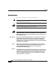
Preface Conventions Conventions This section describes the conventions used in this guide. Note Means reader take note. Notes contain helpful suggestions or references to additional information and material. Caution This symbol means reader be careful. In this situation, you might do something that could result in equipment damage or loss of data. Warning This warning symbol means danger. You are in a situation that could cause bodily injury.
Preface Related Documentation Warnung Dieses Warnsymbol bedeutet Gefahr. Sie befinden sich in einer Situation, die zu einer Körperverletzung führen könnte. Bevor Sie mit der Arbeit an irgendeinem Gerät beginnen, seien Sie sich der mit elektrischen Stromkreisen verbundenen Gefahren und der Standardpraktiken zur Vermeidung von Unfällen bewußt. Avvertenza Questo simbolo di avvertenza indica un pericolo. La situazione potrebbe causare infortuni alle persone.
Preface Obtaining Documentation • Cisco 806 Router Software Configuration Guide • Regulatory Compliance and Safety Information for the Cisco 806 Router and SOHO 71 Router • Configuration Note for the Cisco SOHO 71 Router • The latest version of the Cisco IOS Release Notes You might also need to refer to the following documents: • Cisco IOS Release 12.0 Quality of Service Solutions Configuration Guide • Cisco IOS Security Configuration Guide, Release 12.
Preface Documentation Feedback Registered Cisco.com users (Cisco direct customers) can order a Cisco Documentation DVD (product number DOC-DOCDVD=) from the Ordering tool or Cisco Marketplace. Cisco Ordering tool: http://www.cisco.com/en/US/partner/ordering/ Cisco Marketplace: http://www.cisco.com/go/marketplace/ Ordering Documentation You can find instructions for ordering documentation at this URL: http://www.cisco.com/univercd/cc/td/doc/es_inpck/pdi.
Preface Cisco Product Security Overview Cisco Product Security Overview Cisco provides a free online Security Vulnerability Policy portal at this URL: http://www.cisco.com/en/US/products/products_security_vulnerability_policy.ht ml From this site, you can perform these tasks: • Report security vulnerabilities in Cisco products. • Obtain assistance with security incidents that involve Cisco products. • Register to receive security information from Cisco.
Preface Obtaining Technical Assistance Never use a revoked or an expired encryption key. The correct public key to use in your correspondence with PSIRT is the one that has the most recent creation date in this public key server list: http://pgp.mit.edu:11371/pks/lookup?search=psirt%40cisco.
Preface Obtaining Technical Assistance Note Use the Cisco Product Identification (CPI) tool to locate your product serial number before submitting a web or phone request for service. You can access the CPI tool from the Cisco Technical Support Website by clicking the Tools & Resources link under Documentation & Tools. Choose Cisco Product Identification Tool from the Alphabetical Index drop-down list, or click the Cisco Product Identification Tool link under Alerts & RMAs.
Preface Obtaining Additional Publications and Information Definitions of Service Request Severity To ensure that all service requests are reported in a standard format, Cisco has established severity definitions. Severity 1 (S1)—Your network is “down,” or there is a critical impact to your business operations. You and Cisco will commit all necessary resources around the clock to resolve the situation.
Preface Obtaining Additional Publications and Information troubleshooting tips, configuration examples, customer case studies, certification and training information, and links to scores of in-depth online resources. You can access Packet magazine at this URL: http://www.cisco.com/packet • iQ Magazine is the quarterly publication from Cisco Systems designed to help growing companies learn how they can use technology to increase revenue, streamline their business, and expand services.
C H A P T E R 1 Product Overview The Cisco 806 router and Cisco SOHO 71 router can connect a corporate telecommuter or small office to an Internet service provider (ISP) over a broadband or Ethernet connection to the following sites: • Corporate LANs • The Internet The router is capable of bridging and multiprotocol routing between LAN and WAN ports. Features Table 1-1 summarizes the features of these routers.
Chapter 1 Product Overview Router Overview Table 1-1 Cisco 806 Router and SOHO 71 Router Feature Summary (continued) Feature Routers Description Dynamic RAM (DRAM) Cisco 806 32 MB of DRAM built in. SOHO 71 16 MB of DRAM built in. Ease of installation Both Color-coded ports and cables reduce the chance of installation error. Cisco IOS software Both Support Cisco IOS software.
Chapter 1 Product Overview Router Overview Front Panel Figure 1-1 shows the front panel of the Cisco 806 router. Figure 1-1 Cisco 806 Front Panel OK 1 RXD TX D T 1 2 3 4 RXD COMPUT ERS CISCO 80 0 TXD 51818 INTERNE SERIES Figure 1-2 shows the front panel of the SOHO 71 router. Figure 1-2 SOHO 71 Front Panel OK RXD TX D INTERNE T 1 2 3 4 RXD COMPUT ERS CISCO SO HO TXD 65861 1 SERIES Back Panel Figure 1-3 shows the back panel of the Cisco 806 router.
Chapter 1 Product Overview Router Overview Figure 1-3 Cisco 806 Back Panel Cable lock Physically secures router TO HUB TO PC Ethernet ports Connect to Ethernet network devices ETHERN ET 10BASET COMPUT ERS (E0) Ethernet port Connects to broadband modem or Ethernet switch Model Cis co 806 CONSOL E ETHERN ET 10BAS 3 2 ET +5 VDC 1 51814 4 INTERNE T (E1) TO HUB/TO PC button Determines the Ethernet device and cable type used for Ethernet port 4 Console port Connects to PC or terminal
Chapter 1 Product Overview Router Overview LEDs Table 1-3 summarizes the functions of the LEDs on the routers. Table 1-3 LED Functions LED Color Function OK LED Green On when power is supplied to the router and when the router completes the self-test procedure and begins operating. COMPUTERS 1-4 Green On when an Ethernet device is connected. Blinks when the connection has a problem. See the “Troubleshooting” chapter for more information.
Chapter 1 Product Overview Router Overview Cisco 806 Router and SOHO 71 Router Hardware Installation Guide 1-6 78-10432-04
C H A P T E R 2 Installation This chapter provides information on the following topics: • Preparing for Installation • Preventing Router Damage • Installing Your Router • Verifying Router Operation • Mounting Your Router • Connecting to a Website • What to Do If You Cannot Connect to a Website Preparing for Installation This section provides information on safety, mounting of the router, and unpacking the router box.
Chapter 2 Installation Preparing for Installation Warnings Before installing the router, read the following warnings: Warning Read the installation instructions before you connect the system to its power source. Warning No operator serviceable parts inside. Refer servicing to qualified personnel. Warning Before working on a chassis or working near power supplies, unplug the power cord on AC units; disconnect the power at the circuit breaker on DC units.
Chapter 2 Installation Preparing for Installation Warning To avoid electric shock, do not connect safety extra-low voltage (SELV) circuits to telephone-network voltage (TNV) circuits. LAN ports contain SELV circuits, and WAN ports contain TNV circuits. Some LAN and WAN ports both use RJ-45 connectors. Use caution when connecting cables. Warning Do not work on the system or connect or disconnect cables during periods of lightning activity.
Chapter 2 Installation Preparing for Installation Caution Periodically check the resistance value of the antistatic strap, which should be between 1 and 10 megohms (Mohms). Unpacking the Box Table 2-1 lists the items that come with your router. All these items are in the accessory kit that is inside the box that your router came in. If any of the items is missing or damaged, contact your customer service representative.
Chapter 2 Installation Preventing Router Damage Preventing Router Damage Follow these guidelines when connecting devices to your router: • Connect the color-coded cables supplied by Cisco Systems to the color-coded ports on the back panel. • If you must supply your own cable, see Appendix A for cabling specifications. If this appendix does not provide specifications for a particular cable, we strongly recommend ordering the cable from Cisco Systems.
Chapter 2 Installation Installing Your Router Connecting Ethernet Devices Table 2-2 lists the Ethernet devices you can connect to the router, the connections for each device, and the settings of the router TO HUB/TO PC button (the default setting is IN).
Chapter 2 Installation Installing Your Router Connecting a Hub Before connecting a hub to the router, see Table 2-2 for information on setting the TO HUB/TO PC button. To connect a hub, follow the steps in Figure 2-1. (Figure 2-1 shows a Cisco 806 router, but the process is the same for a SOHO 71 router.) Figure 2-1 Connecting a Hub 1. Set TO HUB/TO PC button. Cisco 806 router TO HUB TO PC 2. Connect yellow cable to ETHERNET port 4 on Cisco 806 router.
Chapter 2 Installation Installing Your Router Connecting a Server, PC, or Workstation Before connecting the server, PC, or workstation, see Table 2-2 to determine how to set the router TO HUB/TO PC button. To connect one of these devices to ETHERNET port number 4, follow the steps in Figure 2-2. (Figure 2-2 shows a Cisco 806 router, but the process is the same for a SOHO 71 router.) Figure 2-2 Connecting a Server, PC, or Workstation 1. Set TO HUB/TO PC button. Cisco 806 router TO HUB TO PC 2.
Chapter 2 Installation Installing Your Router Connecting to the Internet You can use an installed broadband modem or Ethernet switch to connect to the Internet. Connecting a Broadband Modem To connect to an installed DSL, cable, or long-reach Ethernet modem, follow the steps in Figure 2-3. (Figure 2-3 shows a Cisco 806 router, but the process is the same for a SOHO 71 router.
Chapter 2 Installation Installing Your Router Connecting an Ethernet Switch To connect an installed Ethernet switch to the router, follow the steps in Figure 2-4. (Figure 2-4 shows a Cisco 806 router, but the process is the same for a SOHO 71 router.) Figure 2-4 Connecting to an Ethernet Switch ETHERNET TO HUB TO PC 10BASET COMPUTER S (E0) Model Cis CONSOLE co 806 ETHERNET 4 3 2 10BASET +5 VDC 1 INTERNET (E1) 1 SYSTEM 1X RPS MODE 2 3 4 5 6 7 8 9 10 11 60099 1.
Chapter 2 Installation Installing Your Router Figure 2-5 TO HUB TO PC Connecting a Terminal or PC ETHERN ET 4 10BASET COMPUT ERS (E0) Model Cisco CONSOL E 806 ETHERN ET 10BASE T 3 2 +5 VDC 1 INTERNE T (E1) 2. Connect DB-9 connector to terminal or PC. 51821 1. Connect RJ-45 connector on light blue cable to CONSOLE port.
Chapter 2 Installation Verifying Router Operation This equipment is designed to be grounded. Ensure that the host is connected to earth ground during normal use. Warning Figure 2-6 Connecting the AC adapter TO HUB TO PC ETHERN ET 4 10BASET COMPUT ERS (E0) Model Cisc CONSOL E o 806 ETHERN ET 10BASE T 3 2 51820 Cisco 806 router +5 VDC 1 INTERNE T (E1) Desktop power supply 3. Connect power cord to electrical outlet. 1. Connect power supply cable. 2. Connect power cord to power supply.
Chapter 2 Installation Mounting Your Router Table 2-3 Verifying Operation Power/Link LEDs to Check Normal Patterns Power OK On To hub, server, PC, COMPUTERS 4, COMPUTERS RXD, and or workstation COMPUTERS TXD connected to ETHERNET port 4 • COMPUTERS 4 is on when the Ethernet port is physically connected to a hub, PC, or workstation. • COMPUTERS RXD blinks when an Ethernet port receives an Ethernet packet. • COMPUTERS TXD blinks when an Ethernet port sends an Ethernet packet.
Chapter 2 Installation Mounting Your Router Mounting on Table Do not cover or obstruct the router vents, which are located on the router sides. Mounting on Wall You can mount your router on a wall or other vertical surface by using the molded mounting brackets on the bottom of the router and two number-six, 3/4-in. (M3.5 x 20 mm) screws. You must provide the screws. Figure 2-7 shows the mounting brackets. Caution If you are mounting your router on drywall, use two hollow wall-anchors (1/8 in.
Chapter 2 Installation Mounting Your Router The following conditions must be met when you mount the router: • Because you will use the LEDs as status and problem indicators, the front panel must face upward and be easily visible. • The router must be mounted low enough for you to see the LEDs in case you need to troubleshoot a problem. • The power supply must rest on a horizontal surface such as the floor or a table.
Chapter 2 Installation Mounting Your Router Figure 2-8 Mounting Router on Wall 1. Secure two screws 7-5/8 in. (19.35 cm) apart into a wall and 1/8 in. (0.32 cm) from the wall. Wall-mount screw 7-5/8 in. (19.35 cm) Wall 2. Hang router on screws. Screw OK 1/8 in. (0.32 cm) 1 RX IN D TE TX RN D ET CI O 1 SC SE 3 RI ES EC 4 OM PU TE RX RS D 0 2 80 TX D Mounting brackets 51819 Maximum distance 6 ft (2 m) 3. Place power supply on horizontal surface.
Chapter 2 Installation Connecting to a Website Connecting to a Website The router has been configured to work for the most common type of installation. Log onto a PC connected to the router, open a web browser, and connect to a website. If you connected to a website, you have completed setup and can continue to use the router. If you cannot display a website, make sure that the broadband modem or Ethernet switch that the router is connected to is operating, and try again.
Chapter 2 Installation What to Do If You Cannot Connect to a Website Tip If the CRWS home page does not appear when you enter the URL http://10.10.10.1, test the connection between the PC and the router by doing the following: 1. Check that the OK LED on the router is on, and check the cable connection between the router and the PC. Be sure that the TO HUB/TO PC button is in the TO PC position. 2.
C H A P T E R 3 Troubleshooting This chapter describes problems that could occur with the router hardware, possible causes of the problems, and steps for solving the problems. The problems are grouped into the following areas: • Problems During Initial Startup • Problems After Router Is Running For more information on problems that could occur with the software, refer to the Cisco 806 Router Software Configuration Guide.
Chapter 3 Troubleshooting Problems During Initial Startup Problems During Initial Startup Table 3-1 lists problems that a user might encounter when the router is initially booted. Table 3-1 Problems During Initial Startup Symptom Problem Solutions All LEDs, including OK LED, are off. No power to router. Perform the following tasks in order: No connection to modem or Ethernet switch. (Internet LED is off.) No connection to Ethernet devices. (COMPUTER LEDs 1 through 4 are off.
Chapter 3 Troubleshooting Problems After Router Is Running Table 3-1 Problems During Initial Startup (continued) Symptom Problem Solutions Improper setting of TO To make sure that the button is set correctly, see HUB/TO PC button on Table 2-2 in Chapter 2, “Installation.” router or hub. Cannot connect to the Internet • • • Broadband modem or Ethernet switch is not connected or turned on. A problem with the broadband or WAN service.
Chapter 3 Troubleshooting Problems After Router Is Running Table 3-2 Symptom Problems After Router is Running (continued) Problem Connection to the broadband A cable-related or Ethernet line is intermittent problem: or lost. (The INTERNET 1 • Disconnected LED on the front panel is off.) cable. • Damaged cable. Solutions Perform the following tasks in order: 1. Make sure that the connectors at both ends of the cable are secure. 2. Make sure that the cable is not physically damaged.
C H A P T E R A Specifications and Cables This appendix provides system, port, and cabling specifications for the router. System Specifications Table 0-1 outlines the system specifications for the router. Table 0-1 System Specifications Description Design Specification Physical Dimensions Dimensions (H x W x D) 2.0 x 9.7 x 8.5 in. (5.1 x 24.6 x 21.6 cm) Weight (does not include desktop power supply) Cisco 806 router: 1.5 lb (0.
Chapter A Specifications and Cables Port Connector Pinouts Table 0-1 System Specifications (continued) Description Design Specification Router Power AC input voltage 100 to 240 VAC Frequency 50 to 60 Hz Power consumption 15W Voltage 5V For information on regulatory compliance, refer to the Regulatory Compliance and Safety Information for Cisco 806 Router and SOHO 71 Router document that was shipped with your router.
Chapter A Specifications and Cables Port Connector Pinouts Table 0-2 Cisco 806 Router Ethernet Connector Pinouts (RJ-45) Pin Function (TO HUB/TO PC Button – IN Position) Function (TO HUB/TO PC Button – OUT Position) 1 TX+ RX+ 2 TX– RX– 3 RX+ TX+ 4 Unused Unused 5 Unused Unused 6 RX– TX– 7 Unused Unused 8 Unused Unused Table 0-3 Console Connector Pinouts (RJ-45) Pin Function 1 RTS 2 DTR 3 TXD 4 GND 5 GND 6 RXD 7 DSR 8 CTS Cisco 806 Router and SOHO 71 Router
Chapter A Specifications and Cables Cabling Specifications The Console port is configured as a data communications equipment (DCE) device. The default parameters for the console port are as follows: • 9600 baud • 8 data bits • No parity • One stop bit Table 0-4 Power Connector Pinouts Pin Function 1 ROF 2 RTN 3 N.C. 4 N.C. 5 +5 6 RTN 7 N.C. 8 N.C.
Chapter A Specifications and Cables Cabling Specifications Table 0-5 Ethernet Cable Specifications Type Category Shielding 10BASE-T Category 3 or 5 Unshielded twisted-pair (UTP) Maximum Cable Distance Table 0-6 provides the maximum distance of Ethernet cables that you can use between Ethernet devices.
Chapter A Specifications and Cables Cabling Specifications Cisco 806 Router and SOHO 71 Router Hardware Installation Guide A-6 78-10432-04
INDEX Numerics connecting broadband modem 2-9 10BASE-T Ethernet ports 1-1 Ethernet devices 2-6 Ethernet switch 2-10 hubs 2-7 A PC 2-8, 2-10 accessory kit 2-4 power supply 2-11 AC input voltage A-2 server 2-8 adapter, included 2-4 terminal or PC to console port 2-10 altitude specifications A-1 workstation 2-8 console port 1-2 conventions, hazard x B back panel (figure) 1-3 broadband modem, connecting 2-9 D damage, preventing 2-5 C cables documentation related xi dynamic RAM 1-2 Ethernet, t
Index types of 2-6 M Ethernet devices, connecting 2-6 Ethernet switch, connecting 2-10 mounting of the router 2-13 F P feature summary (table) 1-1 PC, connecting 2-8 Flash memory 1-1 pinouts A-2 frequency specifications A-2 power problems 3-2 front panel (figure) 1-3 specifications A-2 power connector, locking 1-2 H power supply, connecting 2-11 hazard statement, defined x problems HUB/NO HUB button settings 2-6 after router is running (table) 3-3 hubs, connecting 2-7 during initial st
Index system A-1 startup problems 3-2 system specifications (table) A-1 T table mounting 2-14 temperature specifications A-1 U unpacking the router 2-4, ?? to 2-4 V voltage specifications A-2 W wall mounting description 2-14 figure 2-16 warnings, installation 2-2 weight specifications A-1 workstation, connecting 2-8 Cisco 806 Router and SOHO 71 Router Hardware Installation Guide 78-10432-04 IN-3
Index Cisco 806 Router and SOHO 71 Router Hardware Installation Guide IN-4 78-10432-04