Cisco SFS 7012 InfiniBand Server Switch Hardware Users Guide Corporate Headquarters Cisco Systems, Inc. 170 West Tasman Drive San Jose, CA 95134-1706 USA http://www.cisco.
THE SPECIFICATIONS AND INFORMATION REGARDING THE PRODUCTS IN THIS MANUAL ARE SUBJECT TO CHANGE WITHOUT NOTICE. ALL STATEMENTS, INFORMATION, AND RECOMMENDATIONS IN THIS MANUAL ARE BELIEVED TO BE ACCURATE BUT ARE PRESENTED WITHOUT WARRANTY OF ANY KIND, EXPRESS OR IMPLIED. USERS MUST TAKE FULL RESPONSIBILITY FOR THEIR APPLICATION OF ANY PRODUCTS.
Contents New and Changed Information Preface v vii Audience vii Organization vii Conventions viii Related Documentation viii Obtaining Documentation, Obtaining Support, and Security Guidelines CHAPTER 1 viii Installation 1-1 Statement 1019—Main Disconnecting Device 1-2 Statement 1045—Short-circuit Protection 1-3 Statement 1074—Comply with Local and National Electrical Codes 1-5 Statement 1075—Hazardous Voltage or Energy Present on DC Power Terminals 1-6 Planning the Installation 1-7 Rack Spe
Contents SFS 7012 Component LEDs 1-28 SFS 7012 Leaf and Spine Module LEDs 1-29 Shutdown Procedures 1-30 Hot Swapping Components 1-30 Hot Swapping Spine and Leaf Modules 1-30 Hot Swapping the Fan Unit 1-31 Hot Swapping Power Supplies 1-31 CHAPTER 2 Operations and Administration 2-1 Chassis Viewer 2-1 The Chassis Viewer Manages 2-2 Home Page 2-2 ? (Help) Button 2-3 Support Button 2-3 Displaying the Leaf and Spine Module Views 2-3 Leaf Module View 2-3 Spine Module View 2-4 Leaf and Spine Module Component
Contents HTTP/CLI Session Configuration 2-19 SNMP 2-20 Target Configuration 2-20 Filter Status 2-23 Setting Community Strings 2-24 Configuration File Administration 2-25 Administer 2-25 Host Upload/Download 2-26 Trap Control 2-28 Chassis Traps 2-29 SFS 7012 Port Statistics 2-32 Port Statistics Field Descriptions 2-33 Leaf and Spine Module IB Port Statistics 2-35 Leaf Modules 2-35 Spine Modules 2-35 Set Field Thresholds 2-36 Time Service 2-38 Configuring the Switch OOB IP Address 2-41 Configuring the Switch
Contents Accessing the CLI B-3 Groups and Commands B-4 General B-4 Deprecated B-19 Chassis B-20 Network B-24 Firmware B-29 SubnetManagement B-34 Log B-49 KeyManagement B-53 IbSwitchInfo B-54 TimeManagement B-68 SNMP B-71 Capture B-76 APPENDIX C Troubleshooting C-1 Hardware Checks C-1 Switch C-1 Problem C-1 Fix C-1 Power Supply C-1 Problem C-1 Fix C-1 Problem C- 2 Fix C-2 OOB Ethernet RJ45 Port C-2 Problem C-2 Fix C-2 SFS 7012 Leaf Module IB Ports Problem C-2 Fix C-2 C-2 Troubleshooting Scenarios C-3
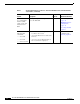
New and Changed Information The Cisco SFS 7012 InfiniBand Server Switch Hardware Users Guide applies to the SFS 7012 Release 3.1 or later. Table 1 lists the new and changed features available with each supported SFS 7012 release.
Table 1 Documented Features for the Cisco SFS 7012 InfiniBand Server Switch Hardware Users Guide (continued) Feature Description User authentication via command line interface (CLI), serial console and Chassis Viewer GUI User login and password required to access the SFS 7024 Changed in Release 4.1.1.1.
Preface This preface describes the audience, organization, and conventions of the Cisco SFS 7012 InfiniBand Server Switch Hardware Users Guide . It also provides information on how to obtain related documentation. Audience The intended audience for this document are network administrators responsible for configuring and operating network equipment.
Conventions This document uses the following conventions for notes, cautions, and safety warnings. Notes and Cautions contain important information that you should be aware of. Note Caution Means reader take note. Notes contain helpful suggestions or references to material not covered in the publication. Means reader be careful. You are capable of doing something that might result in equipment damage or loss of data.
C H A P T E R 1 Installation This chapter describes how to install the Cisco SFS 7012™ and its components, and it includes the following information: Note • Planning the Installation, page 1-7 • Installation Tasks, page 1-12 • Hot Swapping Components, page 1-30 Before you install, operate, or service the system, read the Regulatory Compliance and Safety Information for the Cisco Server Fabric Switches: 7000P, 7000D, 7008P, 7012, 7024, and 3012R for important safety information.
Warning IMPORTANT SAFETY INSTRUCTIONS This warning symbol means danger. You are in a situation that could cause bodily injury. Before you work on any equipment, be aware of the hazards involved with electrical circuitry and be familiar with standard practices for preventing accidents. Use the statement number provided at the end of each warning to locate its translation in the translated safety warnings that accompanied this device.
Aviso A combinação ficha-tomada deverá ser sempre acessível, porque funciona como interruptor principal. ¡Advertencia! El conjunto de clavija y toma ha de encontrarse siempre accesible ya que hace las veces de dispositivo de desconexión principal. Varning! Man måste alltid kunna komma åt stickproppen i uttaget, eftersom denna koppling utgör den huvudsakliga frånkopplingsanordningen.
Aviso Este produto requer proteção contra curto-circuitos (sobreintensidade de corrente), que deve estar instalada nos edifícios. Instale apenas de acordo com as normas de instalação elétrica nacionais e locais. Advertencia Este producto necesita estar conectado a la protección frente a cortacircuitos (sobretensiones) que exista en el edificio. Instálelo únicamente en conformidad con las regulaciones sobre cableado, tanto locales como nacionales, a las que se tenga que atener.
Statement 1074—Comply with Local and National Electrical Codes Warning Installation of the equipment must comply with local and national electrical codes. Statement 1074 Waarschuwing Bij installatie van de apparatuur moet worden voldaan aan de lokale en nationale elektriciteitsvoorschriften. Varoitus Laitteisto tulee asentaa paikallisten ja kansallisten sähkömääräysten mukaisesti. Attention L'équipement doit être installé conformément aux normes électriques nationales et locales.
Statement 1075—Hazardous Voltage or Energy Present on DC Power Terminals Warning Hazardous voltage or energy may be present on DC power terminals. Always replace cover when terminals are not in service. Be sure uninsulated conductors are not accessible when cover is in place. Statement 1075 Waarschuwing Op DC-aansluitingspunten kunnen zich gevaarlijke voltages of energieën voordoen.
¡Advertencia! Puede haber energía o voltaje peligrosos en los terminales eléctricos de CC. Reemplace siempre la cubierta cuando no estén utilizándose los terminales. Asegúrese de que no haya acceso a conductores descubiertos cuando la cubierta esté colocada. Varning! Farlig spänning eller skadlig energi kan finnas i likströmsterminalerna. Sätt alltid tillbaka höljet när terminalerna inte används. Försäkra att inga oisolerade ledare kan nås när höljet sitter på plats.
Cable Requirements Cable Distances When planning the location of the switches, consider the distance limitations for signaling, EMI, and connector compatibility. It is recommended that the user does not exceed specified transmission rate and distance limits. Note Building and electrical codes vary depending on the location. Comply with all code specifications when planning the site and installing cable.
Installation Tasks Checklist To perform the actual switch installation, the site implementation engineer must perform the following tasks, which are detailed in this section. Caution Be sure to review the Safety Information on page 1-9 before starting the installation and during the installation process. Check the installation site to verify the installation of cabinet power feeds, rails, and grounding. Step 1 Unpack the equipment and inspect for any shipping damage.
Warning After installing system components in a rack never pull more than one component at one time out of the rack on its slide assemblies. The weight of more than one extended component could cause the rack to tip over. Warning Do not step on or stand on any component when servicing other components in a rack. Warning The chassis, when fully populated with leaf modules, spine modules, power and fan supplies, is very heavy (approximately 100 lbs.).
Warning To avoid potential electrical shock, operate this unit only when the cover is in place. Warning To avoid potential electrical shock, use only a grounded (three wire) electrical outlet. Warning Keep objects that might damage this unit and liquids that might spill clear from this unit. Liquids and foreign objects that come into contact with voltage points could create the risk of fire or electrical shock. Caution Do not overload the power supply branch circuit providing power to the rack.
Be sure of the following: • The cabinet has a full earth ground to provide reliable grounding. • There is enough room to work on the equipment. • The equipment will have enough clearance for front and rear access. • The IB cables can be accessed easily. • Water or moisture cannot enter the switch. • The ambient temperature stays between 50° - 113°F (5° - 45° C). • Cabinet doors do not interfere with front-to-back air flow. The cabinet should have its own power distribution (with switch).
Step 1 If applicable, remove the doors of the rack. Step 2 Mark the rack, allowing 7 U (12.25 inches) of vertical space to install the SFS 7012 switch. Step 3 Install the support rails. Step 4 Rack mount the switch. Step 5 If applicable, replace the doors of the rack. Mounting Kit The mounting kit hardware contains all of the necessary parts for installing and mounting the SFS 7012 switch into a rack. These kits are intended for use in cabinets with a depth ranging from 28 - 34 inches.
Note The 2 front holes should match up with the top and bottom holes of the rail front flange. All holes should correspond to the rail mounting positions (i.e., the holes marked with pen or tape). Step 2 Fasten the rail back flange (chassis leaf module side) to the rack by installing two screws into the rail and rack.
To install the switch into the rack, perform the following steps: Step 1 Clear the area of any unnecessary materials. Step 2 Attach the clip of the ESD wristband (strap) to bare metal on the cabinet. Put the wristband around one wrist with the metal button against the skin. Step 3 Lift the switch and from the front of the cabinet, slide it onto the rails. The fans and power supplies are on the front of the chassis; leaf modules are to the rear.
Figure 4 Secure Chassis to Rack Install 1 screw and caged nut into each hole above and below the handle Step 6 Using two screws, install the lower mounting bracket to the rail assembly and chassis as shown in Figure 5. Figure 5 Install the Lower Mounting Bracket and Heyclip Install the lower rear mounting bracket to the rail assembly and chassis Install the heyclip here Step 7 Install the heyclip to the rail assembly. Step 8 If applicable, reinstall the chassis fascia(s).
Step 1 On the switch fan side, insert the notches on the top of the fascia into the two slots on the chassis frame. Snap the bottom of the faceplate in place. Removing a Module or Blank The handles are self-locking. To unlock, push up on the handles to disengage from the lock notch. Then gently pull the handles out and slide the module out of the slot. Note If removing, but not replacing a module, remember to replace with a module blank.
Figure 1-6 b. SFS 7012 Chassis — Spine Module Slot Numbering Leaf Modules— Leaf modules should be populated beginning with slot 1, then slot 2, then slots 3 through 12 respectively. Refer to Figure 1-7: Figure 1-7 SFS 7012 Chassis — Leaf Module Slot Numbering Leaf 11 Leaf 12 Leaf 9 Leaf 10 Leaf 7 Leaf 8 Leaf 5 Leaf 6 Leaf 3 Leaf 4 Leaf 1 Leaf 2 Step 2 To install a module or filler, hold it so that the ejector handles are on the bottom. Step 3 Pull the handles out to extend them.
Figure 1-8 SFS 7012 Chassis Front View Figure 1-9 SFS 7012 Chassis Back View Leaf 11 Leaf 12 Leaf 9 Leaf 10 Leaf 7 Leaf 8 Leaf 5 Leaf 6 Leaf 3 Leaf 4 Leaf 1 Leaf 2 AC power inlet for power supplies 1 to 3 RJ-45 for Spine 1 AC power inlet for power supplies 4 to 6 RJ-45 for Spine 2 Step 1 Connect a Category 5 or 6 (Cat 5/6) Ethernet cable to one of the RJ-45 connectors on the SFS 7012. Connect the other end of the Cat 5/6 to the OOB LAN workstation.
Note When handling IB connectors, make certain to remove the connectors by pulling on the center of the lanyard only as shown in Figure 1-10 below. Pulling abruptly on the lanyard, or pulling on only one side of the lanyard will prevent the latch/unlatch operation from occurring, and could damage or break the lanyard. Figure 1-10 4X IB Cable Connector Connecting Power Step 1 Note Provide strain relief for the power cable(s) by feeding them into the heyclips on the lower rail assemblies.
Note If the spine module RS-232 port is connected to a terminal emulation program, the user will be able to view the switch boot process. Be certain to use a null-modem/crossover serial cable for the console port. The settings for the terminal emulation device should be: – 8 data bits – no parity bits – 1 stop bit – 57600 baud – Use VT100 emulation.
• Use the Chassis Viewer GUI from a system that can reach the chassis using the default IP address (192.168.100.9). Using the RS232 Serial Port Step 1 Connect null-modem/crossover serial cables to the RS-232 port of spine 1. If using a terminal emulation device, the settings should be: – 8 data bits – no parity bits – 1 stop bit – 57.6K baud – Use VT100 emulation. – Flow control = XON/XOFF Step 2 Power up the switch. Step 3 The system prompts for a user name.
super The system responds with: Welcome to the SFS 7012 CLI. Type 'list' for the list of commands. Step 6 To change the SFS 7012 default IP address enter: setChassisIpAddr -h ipaddress -m netMask where -h ipaddress is the new IP address in dotted decimal (i.e., xxx.xxx.xxx.xxx) format, and -m netMask is the new subnet mask in dotted decimal (i.e., xxx.xxx.xxx.xxx) format.
Figure 12 SFS 7012 Web Authentication Enter the user name super and password super. Step 5 From the chassis OOB LAN IP submenu, click Set OOB LAN IP. The Set OOB LAN IP is displayed: Step 6 Click in the OOB IP Address field. Figure 13 Set OOB LAN IP Window Step 7 Enter the new switch IP address. Step 8 Click in the Net Mask field. Step 9 Enter the new net mask. Step 10 Click Apply.
Step 13 Enter the new switch default gateway IP address. Step 14 Click Apply. Note A reboot is required to activate the new gateway IP address. Updating Management Spine IP Addresses in a Redundant Management Configuration Note This procedure should be performed the first time the SFS 7012 is powered on. Each managed spine must have a unique IP address that is different than the chassis IP address of the SFS 7012. Therefore, a redundantly-managed SFS 7012 will have three (3) unique IP addresses.
Step 5 At the [boot]: prompt, enter reboot, and press Enter. Upon reboot the managed spine will display information similar to the following: Unified Boot Manager For The T3 Platform. Image Date: Jan 19 2006, 15:03:31 Checking L2 functionality... BCM1125 L2 caches initialized and invalidated CPU0 caches initialized Initialized SMBUS Channels SPD Checksum ok.
CPU0 flushing caches L2 flush complete Start type = 0xBFC006A0 Jumping to romStart Initializing HyperTransport bus HyperTransport initialization completed rintf MBOX connect interrupt_source=28 vector=62 status=0 Printf MBOX intEnable status=0 Found Intel Strata Flash 128 MBit (0x8918). Mounted raw file system on device /image1. (size=6291456 bytes) Mounted raw file system on device /image2. (size=6291456 bytes) Mounted raw file system on device /dump0.
sbe1 speed=100 fullDuplex=1 flowControl=0 Note The command spineip changes the IP address for image1 and image2, SFS 7012 Component LEDs Chassis Status LED The chassis status LED is Green when the system is functioning normally. The chassis status LED is Amber when one of the following conditions exists: • The system ambient temperature exceeds 52 C but remains less than 60 C. • Any Fan Alarm is amber. • Any power supply AC OK LED is off.
• Amber indicates that the following warning condition exists: – A single fan rotation failure at less than 4000 RPM or greater than 10950 RPM. • Red indicates a possible problem, including: – The fan tray is not responding to commands for configuration and temperature-related operations. – A fan is not responding to commands for temperature and speed related operations. – The fan speed has fallen below the minimum allowed RPM for a fan.
– The module can no longer function properly. The system will take the appropriate actions to ensure that no damage is done to its components. • Blinking Amber (once every four seconds) - LED test state. Spine Module Management LEDs Each SFS 7012 spine module has three management LEDs: • Capable: – Green indicates that the spine slot supports management. Off indicates that the spine slot does not support management. – • Stat: – Green indicates that a management board is present.
• Hot swap one module at a time, allowing the chassis to completely update it before hot-swapping the next module. The module update is complete when it becomes visible within the Chassis Viewer GUI. Listed below are the approximate times to fully update each module type: – Spines modules: up to 4 minutes – Leaf modules: up to 2 minutes • When a management spine is hot swapped, the rest of the chassis will continue to move packets without interruption.
Step 8 Tighten the captive panel screw.
C H A P T E R 2 Operations and Administration This chapter describes how to administer and configure the Cisco SFS 7012™ and its components, and it includes the following information: • Logging, page 2-12 • Maintenance, page 2-17 • SNMP, page 2-20 • Configuration File Administration, page 2-25 • Chassis Traps, page 2-29 • SFS 7012 Port Statistics, page 2-32 • Time Service, page 2-38 • Configuring the Switch OOB IP Address, page 2-41 Chassis Viewer The Chassis Viewer is Cisco's browser-base
Figure 1 • SFS 7012 Web Authentication Enter the default user name and password: – Administrator-level user name: super – Administrator-level password: super – Operator-level user name: admin – Operator-level password: admin • The Chassis Viewer home page is displayed. The Chassis Viewer Manages • The SFS 7012 chassis. • Each SFS 7012 leaf module. • Each SFS 7012 spine module. • Logging and monitoring functionality.
? (Help) Button Figure 2-3 Help Button The ? (HELP) button displays online help. Each help screen gives the user a high-level, topic-specific description. Support Button Figure 2-4 Support Button The Support button displays key contact information for support, displayed in the following window: Figure 2-5 Support Contact Screen Displaying the Leaf and Spine Module Views Leaf Module View To display the leaf module view for the SFS 7012: Step 1 Mouse over the leaf module to display.
Figure 2-6 Leaf Module Mouseover Left click the mouse. The leaf module view will be displayed. Figure 2-7 Leaf Module View Spine Module View To display the spine module view for the SFS 7012: Step 1 Mouse over the spine module to display. The edges of the spine module are highlighted green as shown in Figure 2-8 below: Figure 2-8 Spine Module Mouseover Left click the mouse. The spine module view will be displayed.
Figure 2-9 Spine Module View Leaf and Spine Module Component Details Area The Component Details Area contains three areas. • Details Header • Information area. • Menu Figure 2-10 Leaf and Spine Component Details Area Leaf and Spine Details Header The leaf and spine Details Header allows the user to execute the most common tasks for the SFS 7012 switch: • Display the Home page • View field-replaceable unit (FRU) information.
• The gray fields are tied to live data from the selected hardware component as well as live system information. Additionally, the Component Information Area has Apply and Refresh buttons, which perform the following functionality: Apply: Saves any user edits within the white fields to flash memory. Refresh: Refreshes all fields in the information areas.
Figure 2-14 Chassis Viewer Component Details Area Chassis View Component Details Area The Component Details Area contains three areas. • Details Header • Information area. • Menu Chassis Details Header The Chassis Details Header allows the user to execute the most common tasks for the SFS 7012 switch: • Display the Home page • View Log Figure 2-15 Chassis Details Header Rebooting Components from Chassis Viewer Step 1 From the Chassis Details header, click Reboot.
Figure 2-16 Reboot Screen Step 2 Select the radio button of the spine(s) to be rebooted, or select the Reboot Entire Chassis radio button to reboot the SFS 7012 chassis and all spines. Step 3 Click Reboot. Chassis View Component Information Area Figure 2-17 Component Information Area The Chassis View Component Information Area allows the user to monitor important information for each specific hardware component, as well as important system information.
• Fan information • Switch backplane information LEDs and Sensors Tab The LEDs and Sensors tab displays: • Switch component LED information for chassis status, chassis SMA, fan and power supplies. • Slot-based temperature and AC-power sensor data for the internal switching complex. Figure 2-18 LEDs and Sensors Tab Note For a detailed explanation of physical LEDs on the hardware components, please refer to the section SFS 7012 Component LEDs, page 1-28.
System Uptime The elapsed time since the last time switch was re-initialized. System Contact The textual identification of the contact person and their contact information for this system, assigned by the administrator. System Name The name for the system, assigned by an administrator. One convention is to use the system's fully qualified domain name as the System Name. System Location The location of the system, assigned by an administrator.
Status Displays the status of the component. Part Num Displays the part number of the component. Detail A button for each row that displays additional detail about the component. Additional details include: Model, Version, Manufacturer Name, Product Name, Manufacturer Id, Manufactured Date Apply Button Saves any changes made by the user in the Power tab to memory. Refresh Button Refreshes all fields in the Power tab. Fan Tab The Fan tab displays switch fan information.
Configuration and Monitoring Features The following section provides detailed, task-oriented descriptions for configuring and monitoring the SFS 7012 switch and its feature functionality. Chassis View Menu Figure 2-20 Chassis View Menu The Chassis View Menu allows the user to execute all configuration and operation tasks available for the SFS 7012 switch. Logging The Logging submenu allows the user to set and reset levels for the message log file.
Step 1 From the menu, select Logging. Step 2 From Logging, select Set Level. The Log System Configurator (Device Tab) window is displayed: Figure 2-23 Log System Configurator (Device Tab) The Device tab presents current log level configuration settings for the following software modules: – RAM = The circular log buffer contained in memory. To access the contents of this buffer, use the Chassis Viewer View Log button – Syslog = Messages that are sent to a syslog host specified on the Syslog tab.
– FATAL – Indicates that a non-recoverable system problem has occurred. The user should reboot the system or component and verify that the subsystem is fully functional to determine whether the fault has been corrected. If the problem persists, the user should contact the supplier. – ERROR – Indicates that a serious system error has occurred which might be recoverable. If the system exhibits any instability, the user should reboot the system or component.
Figure 2-25 Log System Configurator: Preset Tab To change the log level settings: Step 1 Click the On-Off checkbox to the right of the setting(s). Step 2 Click the Submit button to save any changes. Syslog Tab Figure 2-26 Log System Configurator: Syslog Host Tab The Syslog tab allows the user to configure logging messages to be sent to a syslog host. If the Host IP address is 0.0.0.0, no syslog host is configured, otherwise log messages are sent to the syslog server at a specified IP address and port.
Note To centralize logging for all switches in an IB fabric, the user can configure each switch to point to the same syslog server that has the syslog daemon (syslogd) running. When messages are sent to a syslog server, they will appear in the log as being sent from the IP address of the master spine. Reset Log Levels The Reset Levels button resets the logging levels to their factory default values. Figure 2-27 Reset Levels Button To reset the logging levels: Step 1 From the menu, select Logging.
Maintenance Figure 2-29 Maintenance Menu Note For rebooting information, see Rebooting Components from Chassis Viewer, page 2-7 Firmware Update Figure 2-30 Firmware Update Button The Firmware Update button allows the user to select an alternate firmware file for the SFS 7012. These alternate files are reflected in the drop-down lists in the Firmware Update screen. To download firmware: Step 1 From the menu, select Maintenance. Step 2 Click Firmware Update. The Firmware Update screen is displayed.
Note If there are multiple spine modules, the user can select all applicable slots. Step 4 From the Image to Overwrite drop-down list, choose a firmware image to overwrite. Step 5 In the Firmware Update Package: text box, enter the path to the alternate firmware file. If the path is not known, the user can use the Browse... button to locate it. Step 6 To have the new image become active after the next reboot, check the box in the Boot? Column. Step 7 Click the Update Firmware button.
HTTP/CLI Session Configuration Figure 2-34 HTTP/CLI Session Configuration Button The hyper text transfer protocol (HTTP) and command line interface (CLI) session configuration feature allows the user to set HTTP and CLI session timeout parameters, as well as set security requirements for the switch. The session timeout duration is the length of time that a session remains active if there is no GUI activity. If a session is inactive for a time exceeding the timeout duration, the user will be logged out.
• Step 8 Login Disabled - Does not require username or password. When finished, click the Apply button. SNMP The SNMP submenu allows the user to configure and filter SNMP trap information. Figure 2-37 SNMP Submenu Target Configuration The Target Configuration button displays the SNMP Target Configuration Window, allowing the user to view and edit existing SNMP trap destinations. Figure 2-38 Target MIB Configuration Button To display the Target Configuration window: Step 1 From the menu, select SNMP.
Figure 2-39 SNMP Target Configuration Window The top section of the window, SNMP Target Addresses, allows the user to determine what type of SNMP traps are sent, and where they are sent. The rows provide an area for specifying multiple trap destinations. The bottom section of the window, SNMP Target Parameters, allows the user to configure each trap destination with version, optional security information, and filtering mechanisms.
Note The combination of the Transport Domain and the Transport Address determines the trap destination. • Port Specifies the TCP or UDP port that the SNMP trap is sent. • Timeout Specifies the time (in milliseconds) that the trap sender waits on a response before re-sending the trap. • Retry Count Specifies the number of attempts to be made to send the trap after a timeout condition occurs. Note Timeout and Retry Count are SNMP v2.c and above. Not applicable for v1 traps.
The Message Processing Model to be used when generating SNMP messages for entry. Values for this field are 0 for SNMP v1, 1 for SNMP v2 and 3 for SNMP v3. • Security Model The Security Model to be used when generating SNMP messages using this entry. Values for this field are 1 for SNMP v1, 2 for SNMP v2, or 3 for SNMP v3. • Security Name Security name identifies the entity for whom SNMP messages will be generated. Note This is equivalent to the community string in an SNMP get.
Figure 2-40 Filter Status Button To view the SNMP filter status: Step 1 From the menu, select SNMP Step 2 Click Filter Status. The SNMP Filter Status screen is displayed.
Step 1 Click SNMP Step 2 Click Set Community Strings. The Set Community Strings screen is displayed. Figure 2-43 Set Community Strings Window The first field, "Read Only Comm. Name," is the community string that when specified in an SNMP client, allows read-only access to SNMP fields exported by the SNMP server. The second field, "Read/Write Comm. Name," is the community string that when specified in an SNMP client, allows read and write access to SNMP fields exported by the SNMP server.
Step 2 Click Config File Admin. Step 3 Click Administer. The Configuration File Administration screen is displayed: Figure 2-46 Configuration File Administration Screen Step 4 Click on the line card to be modified. The row changes to orange. Step 5 In the Mode column, click the drop-down and select the configuration file administration mode for a line card.
• Download saved configuration files from the CMU to a server. Figure 2-48 Configuration File Administration - Host Up/Download Step 1 Click the chassis view. Step 2 Click Config File Admin. Step 3 Click Host Up/Download. The Configuration File Upload/Download screen is displayed: Figure 2-49 Configuration File Upload/Download Screen To upload a configuration file from a server to the CMU: Step 1 For a selected module, click the Upload button.
Trap Control The Trap Control screen allows the user to set default trap scenarios related to configuration files. Figure 2-51 Trap Control Step 1 Click the chassis view. Step 2 Click Config File Admin. Step 3 Click Trap Control. The Trap Control screen is displayed: Figure 2-52 Configuration File Trap Control Screen Step 4 Note Step 5 Note Select or deselect the desired trap(s). To generate an immediate trap, click the applicable Gen Trap button. To save settings, click on Apply.
The configuration files have been successfully backed up for a particular slot. • CfgSrvModeDisabled An event has occurred that has caused the slot mode to be set to disabled. The user should resolve the error and reset the mode to the proper value for the affected slot. Note The default settings for this screen are as shown above. The user should not change the defaults unless instructed by Technical Support.
This trap indicates that the chassis failed one or more of its self-test(s). icsChassisTrapSystemReboot This trap indicates that the chassis is in the process of rebooting. icsChassisTrapSystemMgmtSrvcStarted This trap indicates that the internal service used to support the management of the chassis is operational. icsChassisTrapSystemMgmtSrvcAborted This trap indicates that the internal service used to support the management of the chassis has terminated abnormally.
icsChassisTrapPowerSupplyRemoved This trap indicates that a power supply was removed from the chassis. icsChassisTrapPowerSupplyFailed This trap indicates that a power supply has failed and is not operational. icsChassisTrapPowerSupplyEEPROMReadFailure This trap indicates, that an error condition was encountered when reading the EEPROM of the power supply. icsChassisTrapPowerSupplyFanFailed This trap indicates that a power supply fan has failed and is not operational.
SFS 7012 Port Statistics The Chassis View Port Statistics area provides IB port information for all of the external and internal ports of the SFS 7012. Figure 2-55 IB Port Statistics To view port statistical information, do the following: Step 1 From the Chassis View Port Statistics submenu, select IB Port Stats. The IB Port Statistics window is displayed: Figure 2-56 IB Port Statistics Understanding Port Naming Conventions Following is an explanation of the conventions used in the Port Name column.
Note Spine chips are referenced by the spine number and the switch chip identifier. Each spine module contains two switch chips (Switch chip A and B). Port Statistics Field Descriptions Port Name/Port Number: Corresponds to external leaf module number/port number, spine module number/port number, and all interswtich links. Link State: Indicates whether the InfiniBand link associated with the physical port is up or down. Possible values are no state change, down, init, armed, active, and unknown.
InfiniBand Statistics: Transmit 32 Bit Words: The number of 32-bit data words transmitted by the port, not including flow control and VCRC data. Receive 32 Bit Words: The number of 32-bit data words received by the port, not including flow control and VCRC data. Transmit Packets: The number of data packets transmitted by the port, not including flow control packets. Receive Packets: The number of data packets received by the port, not including flow control packets.
Pkey Violations Outbound: Indicates the number of times an invalid PKey was sent. PKeys support an advanced InfiniBand feature for logically partitioning a physical subnet into logical access domains. Raw Violations Inbound: Number of times a raw inbound packet discarded. Raw Violations Outbound: Number of times a raw outbound packet was discarded. Leaf and Spine Module IB Port Statistics To access IB port statistics for a specific leaf or spine module, perform the following steps.
Step 2 From the Spine Port Stats menu, select IB Port Stats. Figure 2-59 Spine Port Stats Menu The spine port statistics window is displayed: Figure 2-60 Spine Port Statistics Window For information on the each IB port statistic field, refer to the section Port Statistics Field Descriptions, page 2-33 Set Field Thresholds The Set Field Thresholds screen allows the user to set, for a specific parameter(s), an error message threshold for the 12 cable ports on the SFS 7012.
Figure 2-62 Set Error Reporting Thresholds Screen Step 3 To change a threshold value for any field: a. Click in the Threshold field. b. Enter a new threshold value. Note c. For those fields with a “Percent of Max” time unit, the user may enter a number from 0 to 100. For those fields with a “1 Second” time unit, the user may enter a number from 1 to 65,535. Click Apply. Note Any port which exceeds the configured thresholds will be displayed as red on the home page.
Note The thresholds for the following fields are set based upon the number of error message which can occur in one second. The value can be from 1 to 65,535. portSymbolErrThresh The threshold for the number of times a 8B10B encoding violation, or a disparity violation was detected on the port. portLinkErrRecvThresh The threshold for the number of times the link error recovery process happened successfully on the port.
Figure 2-63 Switch Time Service To set the system time: Step 1 From the menu, click Time Service. Step 2 Click Set System Time. The System Time Information screen is displayed: Figure 2-64 System Time Information Screen To use NTP: Step 1 Click the Use Network Time Protocol? checkbox. Step 2 Enter the IP address for the NTP server. Step 3 To save, click on Apply.
Step 1 Make sure the Use Network Time Protocol? checkbox is unchecked. Step 2 Set the current date and time using the drop-downs for Month, Day, and Year as well as Hour, Minute, Seconds, and AM/PM. Step 3 To save, click on Apply. Figure 2-66 Time Service - Manual Setup To set time zone and daylight saving time (DST) settings: Step 1 In the Time Zone drop-down, select the correct time zone based upon Greenwich Mean Time (GMT).
Configuring the Switch OOB IP Address To configure the Switch IP address: Step 1 From the OOB LAN IP submenu, click Set OOB LAN IP. Figure 2-68 Set Switch OOB IP Address Button Step 2 Click in the OOB IP Address field. Figure 2-69 Set OOB LAN IP Window Step 3 Enter the correct switch IP address. Step 4 Enter the correct net mask. Step 5 Click Apply.
Figure 2-71 Set Switch Default Gateway IP Address Button Step 2 Click in the Gateway Address field. Figure 2-72 Set Default Gateway IP Window Step 3 Type in the correct switch default gateway IP address. Step 4 Click Apply. Note A reboot is required to activate the new gateway IP address.
Spine View Menu Figure 2-73 Spine View Menu Note For information on IB port statistics refer to the section SFS 7012 Port Statistics, page 2-32. Logging The Logging submenu allows the user to view, set levels, reset levels, and purge the message log file. Figure 2-74 Logging Submenu Viewing the Log The View Log button allows the user to view the message log.
Step 1 From the menu, select Logging. Step 2 Click View Log. The log message window is displayed: Figure 2-76 Sample Message Log To save a log message for further analysis, perform the following steps: Step 1 From the Messages window, select Edit, Select All (or CTRL + A). Step 2 Select Edit, Copy (or CTRL + C). Step 3 Open a text editing package, such as Notepad. Step 4 Select Edit, Paste (or CTRL + V). Step 5 Save as a plain text (.txt) file.
Figure 2-78 Purge Log Confirmation Window Step 3 Click OK. Step 4 The message log file is now purged. Maintenance Select Boot Image The Select Boot Image button allows the user to choose an alternative boot image for the SFS 7012. To select a boot image: Figure 2-79 Select Boot Image Button Step 1 From the menu, select Maintenance. Step 2 Click Select Boot Image.
License Keys; Key Administration The License Key submenu allows the user to activate and deactivate feature functionality that is sold as an add-on to the SFS 7012. Adding a New License Key Step 1 Click License Keys. The Key Administration button is displayed: Figure 2-81 License Key Submenu Step 2 Click Key Administration. The Key Management window is displayed: Figure 2-82 Key Management Window Step 3 To add a new license key, click the Add Key button.
Step 3 To delete a license key, click the Delete button. The system prompts with the following: Figure 2-85 License Key Delete Prompt Step 4 Click OK to delete.
Cisco SFS 7012 InfiniBand Server Switch Hardware Users Guide 2-48 OL-8787-05
A P P E N D I X A Technical Specifications Table A-1 SFS 7012 Technical Specifications Switch Physical Dimensions Weight Cooling Environmental • 7U high (24.5”) • 19" rack mount (17.32" wide) • • • 25 3/4" deep (without cables) 100 lb.
Table A-1 SFS 7012 Technical Specifications Power Supply Certification Marks • Up to six redundant, hot plug supplies • 90/264 VAC operation • 350W max power per supply • Input: • 90–264 VAC, 50-60Hz, 1 Phase, 4.0A max current at 115VAC • Inrush Current: • 15A @ 115VAC (25°C cold start) 30A @ 230VAC (25°C cold start) • Power Factor 0.
A P P E N D I X B Command Line Interface This appendix includes the following information: • Commands and Functional Groups, page B-2 • Accessing the CLI, page B-3 • Groups and Commands, page B-4 Overview This section details the usage of the Command Line Interface (CLI) feature for the Cisco SFS 7012™. The CLI allows the user to perform remote configuration and management tasks, which in many respects mirrors the functionality of the Chassis Viewer GUI.
The CLI is also accessible through the RS232 serial port of the SFS 7012. Providing access through the serial port means that users will always have access to the SFS 7012, even if Telnet and SSH are not functioning. Commands and Functional Groups The list of available commands can be accessed by typing list. To keep the list short, the commands are grouped into functional groups, which are: General: General administrative commands Deprecated: Commands that have been deprecated.
Provides commands for configuring SNMP trap destinations and security parameters required to access the SFS 7012 from an SNMP manager. Capture: Provides commands for capturing switch-specific information for the purposes of analysis and debugging. To list commands within a functional group, simply type in the functional group name. For example, to list all of the firmware commands, type Firmware.
Step 2 The system prompts for a username. The CLI has the following default user names: – Operator access: admin – Administrator access: super Type the appropriate username and press Enter. Step 3 The system prompts for a password. The CLI has the following default passwords: – Operator access: admin – Administrator access: super Type the appropriate password and press Enter. The system responds with: Welcome to the SFS 7012 CLI. Type 'list' for the list of commands.
NOTES: General Help Type list or ? for the list of commands. To get help on a particular command type: commandname help. For convienence purposes you can also type: help commandname Use the Up and Down arrow keys to browse command history, Left and Right arrow keys to edit the current command and the Tab key for tab completion of a command. Two alternate key bindings exist for the backspace and delete keys. If these keys are not responding as expected use the swapBsDel command to swap the bindings.
history Displays the history of a command. Syntax: history Options: None. Sample Output: -> history command history [30 max lines]: list Deprecated Network Firmware Log IbSwitchInfo TimeManagement Snmp Ethernet help list history reboot Reboots the device. Syntax: reboot [now][-m][slot n][-s][-n][all] Options: now Does not prompt the user before rebooting. -m Reboot Master (local) Spine 1 (non-disruptive). slot n reset specific device where n = slotNumber (disruptive).
Sample Output: -> reboot Disruptive reboot selected Proceed with reboot? [N] NOTES: You may reboot the local (Master) Spine or the remote (Slave) Spine with one or multiple arguments. Non-disruptive arguments will not interfere with switch traffic. Providing argument all performs disruptive reboot of all present Spines and cards. If rebooting the local device from telnet, ssh, etc., you will have to reconnect after rebooting. Default (no arguments) reboots local device disruptively after prompt.
NOTES: Displays a list of currently active CLI sessions. Note that a session can be 'active', but no user information available (in most cases, this indicates the session is waiting for the user to enter login information).
setTermWidth Change the terminal width for text formatting purposes. Syntax: setTermWidth width Options: width Width of the user’s terminal window. Minimum width is 20 characters. Sample Output: -> setTermWidth 100 NOTES: Allows modification of the terminal width used for text formatting purposes. Note that not all commands adhere to this setting. The minimum width is 20 characters. getTermWidth Displays the terminal width for text formatting purposes. Syntax: getTermWidth Options: None.
NOTES: This changes the prompt for all CLI sessions. The prompt may not exceed 11 characters and is not saved across reboots. If the prompt contains a space, asterick, comma, parenthesis or semicolon it must be enclosed with double quotes ". For example: "*a prompt*". Also, if a prompt is not accepted try to enclose it with double quotes. showLastRetCode Display the return code from the last executed command. Syntax: showLastRetCode Options: None.
Sample Output: -> rcmd NOTES: This command allows users to open a terminal to local I/O devices within the chassis/hemisphere. The command rcmd is an alias of rlogin. See also hostShow. resetCard Reboot a specific slot in the chassis. Syntax: resetCard n [now] Options: n Chassis slot number. now No prompt before resetting the card. Sample Output: -> resetCard 2 now NOTES: If you reset the switch you are connected to you will have to reconnect.
Options: [user] Name of user account to change to. Sample Output: -> user operator User changed to: operator NOTES: Use this command to change to the 'operator' account, or to the 'admin' account. passwd Change users password(s). Syntax: passwd [username] Options: [username] Name of the user whose password needs to be changed. Sample Output: -> passwd operator1 User password changed successfully NOTES: Allows the modification of the user's password. userAdd Add a user account.
Sample Output: -> userAdd admin testuser testpass User added: testuser -> During a Telnet session, if a user is added with userAdd the first time that user attempts to log in the user will see a message: Please change your passwords now. Use Control-C to exit or press 'Enter' key to proceed. If the password is not entered (ie Ctrl+C is done) then the next time this user logs in the same message will be presented.
Options: None. Sample Output: -> userListShow username operator1 USERID Bob role operator admin admin loginMode Change the login authentication mode. Syntax: loginMode [mode] Options: [mode] 0-3, 0 = Username/password required, 1=username required, 2=no authentication, 3=LDAP authentication. Sample Output: -> loginMode 1 Mode successfully changed to: 1 = Password is not required NOTES: This sets the authentication for the CLI.
setldapSvrPort Modify the LDAP Server Port. Syntax: setldapSvrPort [port] Options: [port] The Port of the ldap server you wish to set to authenticate. Sample Output: -> setldapSvrPort 1 NOTES: This sets the LDAP server port. The LDAP server will be contacted for remote authentication. idleTimeoutGet Get the CLI and Chassis Viewer GUI idle timeout values. Syntax: idleTimeoutGet Options: None. Sample Output: -> idleTimeoutGet CLI timeout is 600 seconds. GUI timeout is 0 seconds.
Sample Output: -> idleTimeoutSet 700 CLI timeout is set to 700 seconds. NOTES: Modifies the idle timeout for the CLI or GUI interfaces. Timeouts are in number of seconds, with zero meaning the timeout is disabled. sessionTimeoutDisable Disable the idle timeout for the current CLI session. Syntax: sessionTimeoutDisable Options: None. Sample Output: -> sessionTimeoutDisable Disabled session idle timeout. sessionTimeoutEnable Enable the idle timeout for this CLI session.
Sample Output: -> loginMsgGet Welcome message: Be certain to logout when you are finished using the CLI. NOTES: Displays the current login welcome message for the CLI. This message can be customized with the loginMsgSet command. loginMsgSet Set the CLI login message for this device. Syntax: loginMsgSet [message] Options: [message] The login message (should be encapsulated in quotes “ “). Sample Output: -> loginMsgSet "Be certain to logout when you are finished using the CLI.
Syntax: loginNameSet Options: None. Sample Output: -> loginNameSet NOTES: The login name is an arbitrary string displayed prior to a user attempting a login to a new CLI session. This command modifies this string. serialAuthGet Displays the current serial authentication status. Syntax: serialAuthGet Options: None. Sample Output: -> serialAuthGet NOTES: Displays whether user login and authentication is required on the serial console of the system.
NOTES: This command is used to enable or disable user authentication on the serial console. Use 1 as the only parameter to enable authentication, or 0 to disable authentication. exit Exit the CLI. Syntax: exit Options: None.
Chassis hwMonitor Displays current port states, fan speeds, temperatures, and voltages. Syntax: hwMonitor slot Options: [slot] Slot number to display. 0 for current slot of the management board.
NOTES: Entering this command with no parameters displays the current Node Description. The -d option will display the unit's default value. setIBNodeDesc Changes the IB Node (SMA) Description. Syntax: setIBNodeDesc "New Node String" Options: None. Sample Output: -> setIBNodeDesc "Upper Hemisphere in Rack 1" NOTES: New node name must be enclosed in quotes. Node name must be less than 128 characters. fruInfo Displays the EEProm contents.
chassisQuery Displays information about the line cards in a chassis. Syntax: chassisQuery [slot] [-showType] [-type card_type] [-ignoreInvalidType] Options: [slot] slot number [-showType] display the card type [-type card_type] display slots that have given card type [-ignoreInvalidType] do not return an error if an invalid card type is supplied NOTE: Entering this command with no parameters will display all currently occupied card slots.
showInventory Displays a detailed list of all hardware within the chassis. Syntax: showInventory Options: None.
Network ifShow Displays information for all the network interfaces for the switch, including the management port and the internal Ethernet network. Syntax: ifShow [ifName] Options: [ifName] The network interface name. Sample Output: MasterSpine2-> ifShow sbe0 (unit number 0): Flags: (0x8063) UP BROADCAST MULTICAST ARP RUNNING Type: ETHERNET_CSMACD Internet address: 172.26.2.6 Broadcast address: 172.26.15.255 Internet address: 172.26.2.25 Broadcast address: 172.26.15.
NOTES: In the sbe0 output, the first Internet Address shown is the spine IP address. The second Internet Address shown is the chassis IP address. routeShow Displays the OOB LAN IP routes. Syntax: routeShow Options: None. Sample Output: -> routeShow ROUTE NET TABLE destination gateway flags Refcnt Use Interface ---------------------------------------------------------------------0.0.0.0 172.26.0.254 3 2 1470 mgmt_eth1 172.26.0.0 172.26.0.
Sample Output: PING 172.26.0.254: 56 data bytes 64 bytes from 172.26.0.254: icmp_seq=0. time=0. ms 64 bytes from 172.26.0.254: icmp_seq=1. time=0. ms 64 bytes from 172.26.0.254: icmp_seq=2. time=0. ms 64 bytes from 172.26.0.254: icmp_seq=3. time=0. ms 64 bytes from 172.26.0.254: icmp_seq=4. time=0. ms ----172.26.0.
NOTES: Changing the chassis IP address will drop the connection to the CLI if not using the console port, and may cause the device to become unreachable. showDefaultRoute Displays the default gateway IP address. Syntax: showDefaultRoute Options: None. Sample Output: -> showDefaultRoute Gateway IP Address: 172.26.0.254 NOTES: This is the IP address for the default gateway to route packets from the OOB mangement port to an external network. setDefaultRoute Change the default gateway IP address.
Sample Output: -> arpShow LINK LEVEL ARP TABLE destination gateway flags Refcnt Use Interface -------------------------------------------------------------------------172.26.0.203 00:11:25:c3:07:c5 405 0 0 mgmt_eth1 172.26.0.254 00:11:25:c3:07:c5 405 1 1419 mgmt_eth1 -------------------------------------------------------------------------- hostShow Displays a list of remote hosts names, internet address and alias(es). Syntax: hostShow Options: None.
Firmware fwUpdateSlot Updates the firmware on a specific line card. Syntax: fwUpdateSlot slotnumber [host user password dir filename] Options: slotnumber The chassis slot numberto update. host The name of the host where the firmware file resides. user The FTP user name. password The FTP user password. dir After logging in, the directory to cd to. filename The name of the firmware file. Sample Output: -> fwUpdateSlot 1 Enter 1 for FTP, 2 for local file: 1 Ftp Server IP Address:[192.168.0.
Options: (all,management) Type of card to update. See notes for details. noprompt Will not prompt the user for ftp information (uses the saved values). reboot Upon successful completion, reboots the updated cards . Sample Output: -> fwUpdateChassis all reboot NOTES: Firmware update works by retrieving the firmware file from an ftp server. The file is saved locally and then written to flash. Using the ’all’ option, all cards in the chassis will be updated.
fwSetUpdateParams Change the default update firmware settings. Syntax: fwSetUpdateParams -c cardtype [-h hostname] [-u username] [-p password] [-d directory] [-f filename] Options: -c - cardtype Choices are: 'manangement', 'vfx', 'vex', 'ibx'. -h - hostname The host name or IP address of the FTP server. -u - username The name of the user accessing the ftp server. -p - password The password of the user accessing the ftp server. -d - directory The directory containing the firmware file.
Options: -slot The slot number in the chassis. -all All slots in the chassis. Sample Output: -> showLastScpRetCode 101 SCP: Slot 101 Last Exit Code: 0: Success NOTES: This allows for automated systems to determine if a SCP firmware push was successful or not. fwVersion Displays the firmware versions for a unit. Syntax: fwVersion [slot] Options: slot Slot number. Sample Output: -> fwVersion Slot 105 Information ----------------Firmware Version: 4.1.1.1.
Options: -slot Slot number. -active Displays the version of the active firmware image. -alternate Displays the version of the alternate firmware image. -all Displays the versions for the primary and alternate firmware images. Sample Output: -> bootQuery 105 -all Primary firmware version: 4.1.1.1.11 Alternate firmware version: 3.4.0.11.3 Active firmware version: 4.1.1.1.11 bootSelect Select the next boot image to be used.
Sample Output: -> bootSelect 105 -noprompt Currently installed firmware versions index : alias : version -------------------------*# 1 : image1 : 4.1.1.1.11; 2 : image2 : 3.4.0.11.3; * - indicates Default image (will run at next reboot) # - indicates Active image Default boot image index = 1 NOTES: This command allows the user to set the next boot image for the device. A '*' next to the image entry indicates the currently selected bootimage. A '#' indicates the currently active bootimage.
Syntax: smConfig Options: None. Sample Output: -> smConfig Start at boot? [Y] Start on slave CMU? [N] MasterSpine1-> NOTES: Use this command to configure the subnet manager. Note that for runtime-type parameters the Subnet manager may need to be restarted for them to take effect. smShowLids Display all fabric LID information as known by the subnet manager. Syntax: smShowLids Options: None.
NOTES: Use this command to display the current LID assignments for the devices in the InfiniBand fabric.
smShowPriority Get the priority of the embedded subnet manager. Syntax: smShowPriority Options: None. Sample Output: -> smShowPriority The SM Priority is 0 NOTES: Use this command to display the priority of the subnet manager. smSetPriority Set the priority of the embedded subnet manager. Syntax: smSetPriority Options: None. Sample Output: -> smSetPriority 0 The SM Priority has been set to 0 NOTES: Use this command to set the priority of the subnet manager. Valid values are 0-15.
NOTES: Use this command to set the sweep rate (in seconds) of the subnet manager. Valid values are 3-86400, or 0 to turn the sweep off. bmSetSweepRate Set the sweep rate of the embedded baseboard manager. Syntax: bmSetSweepRate [sweepRate} Options: sweepRate Valid values are 30-86400, or 0 to turn the sweep off. Sample Output: -> bmSetSweepRate NOTES: Use this command to set the sweep rate (in seconds) of the baseboard manager. Valid values are 30-86400, or 0 to turn the sweep off.
NOTES: Use this command to force a sweep by the baseboard manager. smShowGroups Display multicast group information in the embedded subnet manager. Syntax: smShowGroups [-h] Options: -h Display the host name as part of the output.
Sample Output: -> smShowServices ****************************************************************** There is 1 Service Records ********************************************************* Service ID = 0x1100D03C34834444 Service GID = 0xFE80000000000000:00066A000600013C Service P_Key = 0x0000 Service Lease = infinite Service Key = 0x00 0x00 0x00 0x00 0x00 0x00 0x00 0x00 0x00 0x00 0x00 0x00 0x00 0x00 0x00 0x00 Service Name = Service Rev 1.
Sample Output: -> smShowSubscriptions ****************************************************************** There are 2 subscriptions ****************************************************************** Subscriber GID = 0xFE80000000000000:00066A00D8000163 Subscriber LID = 0x0071 Subscriber PKey = 0xFFFF Subscriber Start LID = 0x0001 Subscriber End LID = 0xBFFF Subscriber Record ID = 0x00000001 Subscriber Inform Info = GID = 0x0000000000000000:0000000000000000 Start LID = 0xFFFF End LID = 0x0000 Is Generic? = Yes
Sample Output: -> smShowMasterLMC Master SM LMC: 0 (1 LID(s) per port) NOTES: Use this command to display the Master SM's LMC value to be used on CA ports. smSetMasterLMC Set the SM's LMC value to be used on CA ports. Syntax: smSetMasterLMC Options: None. Sample Output: -> smSetMasterLMC 1 NOTES: Use this command to set the SM's LMC value to be used on CA ports. The default is zero. smShowMasterLid Display the LID of the subnet manager. Syntax: smShowMasterLid Options: None.
Sample Output: -> smShowLidMap ---------------------------------------------------------------------------------SM is currently in the MASTER state, with Topology Pass count = 341 ---------------------------------------------------------------------------------Lid 0x0001: guid = 0x00066a000600013c, pass = 341, SFS 7024 GUID=0x00066a00da000100 172.26.2.2 Spine 1, Ch Lid 0x0002: guid = 0x00066a0007000170, pass = 341, SFS 7024 GUID=0x00066a00da000100 172.26.2.
Options: hoq-lifetime Sample Output: -> smSetHoqLife 11 The SM Head of Queue Lifetime has been set to 11 NOTES: Use this command to set the head of queue lifetime in the subnet manager. smSetVLStall Set the VL stall value in the subnet manager. Syntax: smSetVLStall [vl-stall] Options: vl-stall Sample Output: -> smSetVLStall 7 The SM VL Stall value has been set to 7 NOTES: Use this command to set the VL stall value in the subnet manager.
Sample Output: -> smShowSMParms SM priority is set to 0 SM LMC is set to 0 SM sweep rate is set to 300 SM max retries on receive set to 3 SM max receive wait interval set to 250 millisecs switchLifetime set to 13 HoqLife set to 11 VL Stall set to 7 packetLifetime constant is set to 18 Dynamic PLT ON using values: 1 hop=16, 2 hops=17, 3 hops=17, 4 hops=18, 5 hops=18, 6 hops=18, 7 hops=18, 8+hops=19 MasterSpine1-> NOTES: Use this command to display a sampling of subnet manager parameters.
Sample Output: -> smShowPKeys Index: 0 PKey: 0xffff Desc: Default PKey NOTES: PKeys are used for partitioning the subnet. Only configure PKeys if it is supported by the host driver. smSetKey Set the subnet manager key (SMInfo) value. Syntax: smSetKey MKey Options: None. Sample Output: -> smSetKey MKey NOTES: Use this command to set the SM key. The subnet manager must be offline and key value is up to 8 byte hex. smShowKey Display SMInfo key of the Subnet manager. Syntax: smShowKey Options: None.
Sample Output: -> sm SetMKey SM MKey: 0x0 NOTES: Use this command to set the SM management key. SM must be offline and mkey value is up to 8 byte hex. smShowMKey Displays the management key (MKey) of the subnet manager. Syntax: smShowMKey Options: None. Sample Output: -> sm ShowMKey SM MKey: 0x0 NOTES: The Management Key is used to authorize priviledged subnet operations such as inititializion aliases and configuration.
smSetDefBcGroup Set a default broadcast group in the subnet manager. Syntax: smSetDefBcGroup [clear] | [pKey] [mtu] [rate] [sl] [qKey] Options: clear Clear the configuration. pKey Partition Key. 0 defaults to use the default PKey at index 0. mtu Maximum tranfer unit. 0 will default to use the port's mtu. rate Data Rate. 0 will default to use the port's current rate. sl Service level. qKey Queue Key. If no value entered, defaults to 0..
smSetGidPrefix Set the subnet's Subnet Prefix (default=0xfe80000000000000). Syntax: smSetGidPrefix Gid Prefix Options: None. Sample Output: -> smSetGidPrefix Gid Prefix NOTES: Use this command to set the SM's Subnet Prefix. SM must be offline and Subnet Prefix value is 8 byte hex. smShowGidPrefix Display Subnet manager's Subnet Prefix. Syntax: smShowGidPrefix Options: None. Sample Output: -> smShowGidPrefix NOTES: The Subnet manager's assigned Subnet Prefix (default=0xfe80000000000000).
NOTES: Use this command to tune the SM to handle the configured fabric size. This should be expressed in terms of the upper limit of HCA ports on the subnet. Setting this value will not take effect until the Subnet Manager is restarted. smShowSubnetSize Display the size of the subnet. Syntax: smShowSubnetSize Options: None. Sample Output: -> smShowSubnetSize NOTES: This value is used to tune the SM to handle the configured fabric size, expressed in terms of HCA ports. Log logShow Displays the log file.
Sample Output: -> logshow W|2006/10/04 20:26:31.176U: Thread "Log" (0x8fdab3b0) Log: Unable to Send Trap: 523:Bad:65535 W|2006/10/04 20:26:31.176U: Thread "CPU1" (0x1) Fcpi: Target Device 1 (2e7 p1) NPort Id 0x0106d1: Connection Restored W|2006/10/04 20:26:31.196U: Thread "Log" (0x8fdab3b0) Log: Unable to Send Trap: 523:Bad:65535 W|2006/10/04 20:26:31.216U: Thread "CPU1" (0x1) Fcpi: Target Device 2 (b31 p2) NPort Id 0x0106d2: Connection Restored W|2006/10/04 20:26:31.
Options: None. Sample Output: -> logConfigure Type Q or X to exit. Please enter the number corresponding to what you want to configure. index : name : description -------------------------1 : Device : Logging device. (IE. Ram, syslog, etc) 2 : Preset : General log filter.
Sample Output: -> logResetToDefaults Log configuration has been reset logSyslogConfig Configure the syslog host IP address. Syntax: logSyslogConfig [-h xxx.xxx.xxx.xxx] [-p xxxx] [-f xx] Options: -h ip_address Sets the host IP address in dotted decimal format (xxx.xxx.xxx.xxx). -p port The host port number on which the syslog server is listening. -f facility The syslog facility to use in the messages. Sample Output: -> logSyslogConfig -h 172.26.0.
Sample Output: -> logShowConfig Log Configuration for Slot 3: -----------------------------Configurable devices index : name : |D|F|E|A|W|P|C|I|P|1|2|3|4|5| ---------------------------------------------------1 : Ram : |X|X|X|X|X|X|X|X|X| | | | | | 2 : BriefRam : | | | | | | | | | | | | | | | 3 : Console : |X|X|X|X|X|X|X|X|X| | | | | | 4 : Trap : |X|X|X|X|X| | |X| | | | | | | 5 : Syslog : |X|X|X|X|X|X|X|X|X| | | | | | Configurable presets index : name : state -----------------------------1 : Dump : Enabled
NOTES: License keys unlock various software features of the product. addKey Add a license key. Syntax: addKey [key] Options: -key The license key to add. Sample Output: -> addKey XXxxx-YYYYY-ZZZZZ-11111-222222-3 removeKey Remove a license key. Syntax: removeKey Options: None.
• ismChassisSetEnable • ismPortDisable • ismPortSetSpeed • ismIslSet12x • ismChassisSetMtu • ismIslSetSpeed ismPortStats Displays link error information associated with each switch port. These statistics include errors, dropped packets, discarded packets, and invalid packets. Syntax: ismPortStats [-clear] [-noprompt] [-cols X] [-port X] [-leaf X] [-spine X] Options: -clear Clears the statistics. Statistics are displayed first, then cleared.
Sample Output: -> ismPortStats -spine 3 Name S6AL09 S6AL15 S6AL19 S6AL11 S6AL21 S6AL23 S6AL01 S6AL03 PhysState Up Up Up Up Up Up Up Up PortState Act Act Act Act Act Act Act Act LinkWidth 4X 4X 4X 4X 4X 4X 4X 4X LinkSpeed 5.0Gbps 5.0Gbps 5.0Gbps 5.0Gbps 5.0Gbps 5.0Gbps 5.0Gbps 5.
Syntax: ismPortCounters [-clear] [-active] [-errors] [-potential] [-noprompt] Options: -clear Clears the counters. Counters are first displayed, then cleared. -active Displays only the counters for ports in the active state. -errors Displays only the counters for ports with receive symbol errors. -potential Displays only the counters for ports with active link or width under their maximum supported value.
Syntax: ismLinearFwdb [switch] Options: -switch switch number. Sample Output: -> ismLinearFwdb Switch Leaf 3 Linear Fwdb: LID :: Port 0001 19 (L03S1Aa) 0002 0 ( ) 0003 12 (L03P12 ) 0004 13 (L03S1Ba) Switch Spine 1-A Linear Fwdb: LID :: Port 0001 0 ( ) 0002 9 (S1AL03a) 0003 9 (S1AL03a) 0004 11 (S1AL03b) ismMultiFwdb Show Multicast Forwarding Database for switch. Syntax: ismMultiFwdb [switch] Options: -switch Switch identifier.
Syntax: ismAutoClearConf [disable | enable [warn] [log_first]] Options: -enable Enable the auto-clear feature. -disable Disable the auto-clear feature. -warn Generate warning log messages instead of the default information messages. -log_first Log first clear (otherwise the first clear is not logged). Sample Output: -> ismAutoClearConf enable Auto clear is enabled Note This feature will log every time a counter has reached its maximum capacity.
Note This command works only on platforms supporting 12X link aggregation. The option portName is case sensitive. If it contains spaces, it must be bounded by quotes (e.g., ismPortSet12x "Cable 1", 1). Using this command without the option enable12xBit displays the current values of the port. Devices with affected ports MUST BE REBOOTED to activate changes made with ismPortSet12x.
ismChassisSetSpeed Allows the user to view and set port link speeds (including external ports) for the entire chassis to 2.5 (SDR), 5.0 (DDR) or AutoNegotiate. Syntax: ismChassisSetSpeed [speed] Options: -speed 1=2.5, 2=5.0 or 3=AutoNegotiate.
Note The option portName is case sensitive. If it contains spaces, it must be bounded by quotes (e.g., ismPortEnable "Cable 1"). A reboot is required to activate changes made with this command. This reboot will be disruptive and will cause the affected switch chips to be reset and have a part of their EEPROM to be reloaded.
Note The option port is case sensitive. If it contains spaces, it must be bounded by quotes (e.g., ismPortEnable "Cable 1"). A reboot is required to activate changes made with this command. This reboot will be disruptive and will cause the affected switch chips to be reset and have a part of their EEPROM to be reloaded. ismPortSetSpeed Allows the user to view and set port speeds. Syntax: ismPortSetSpeed port [speed] Options: -port Port name. -speed The port speed (1=SDR, 2=DDR, 3=AutoNegotiate).
Note This command works only on chassis supporting 12X link aggregation. This command enables 12X link aggregation so that internal switching will be 12X. External ports remain configured to 4X and do not require special cabling configuration to function correctly. Using this function without the option enable12xBit displays current values of a port. A reboot is required to activate changes made with this command.
Note This command works only on chassis supporting DDR links. This command sets inter-switch link speeds to either 2.5, 5.0, or AutoNegotiate. External ports remain configured to SDR rate (2.5) and do not require special cabling configuration to function correctly. Using this command without the option enable12xBit displays the current values of the port. A reboot is required to activate changes made with this command.
– 8 portLinkDowned: link error recovery process failed – 9 portRecvErr: errors received – 10 portRecvRemPhysErr: remote physical errors received – 12 portXmitDiscard: port transmit discards – 13 portPKeyViolIn: PKey inbound was invalid – 14 portPKeyViolOut: PKey outbound was invalid – 15 portRawViolIn: raw inbound packet discarded – 16 portRawViolOut: raw outbound packet discarded – 17 portLocalLinkInteg: link integrity errors – 18 portExcBufferOverrun: excessive buffer overrun errors – 19 portRelayedVL15Dr
– portRecvRemPhysErr – portXmitDiscard – portPKeyViolIn – portPKeyViolOut – portRawViolIn – portRawViolOut – portLocalLinkInteg – portExcBufferOverrun – portRelayedVL15Dropped – portLocalVL15Dropped – portNonSMPDropped Cisco SFS 7012 InfiniBand Server Switch Hardware Users Guide B-68 OL-8787-05
TimeManagement time Configure the time on the device. Syntax: time -S ipaddr | -T hhmmss[mmddyyyy] Options: -S ipaddr Sets the NTP Server IP address. -T hhmmss[mmddyyyy] Set the local clock time hour, minutes, and seconds along with the month, day, and year. Sample Output: -> time -S 172.26.0.254 Configured the NTP server ip address successfully 13:53:02 10/06/2006 Configured to use NTP server IP address: 172.26.0.
Note The offset parameter specifies a time zone the system should use when setting the time. In the U.S. the following time zones are in effect: Eastern Standard Time = GMT -5; Central Standard Time = GMT -6; Mountain Standard Time = GMT -7; Pacific Standard Time = GMT -8. GMT = GreenwichMean Time.. timeDSTConf Configure and display the Daylight Saving Time settings.
Options: numSeconds New timeout setting. Sample Output: -> timeNtpTimeout Current NTP timeout value: 2 seconds -> timeNtpTimeout 3 Current NTP timeout changed to 3 seconds Note With no arguments, this command displays the current NTP timeout settings. This is the amount of time (in seconds) for the system to wait for a response from the NTP server. This setting can be configured by using the same command with the new timeout value (in whole seconds) as the only argument.
SNMP snmpCommunityConf Displays and allows the changing of the SNMP community strings. Syntax: snmpCommunityConf [-r readonly_comm_str] [-w read_write_comm_str] Options: -r A read-only community string. -w A read/write community string. Sample Output: -> snmpCommunityConf -r public Read Only Community String Was Set To: public Note If no options are entered the current SNMP read-only community string and read-write community string is displayed.
Options: show Displays the contents of the snmpTargetAddrTable. add Adds a row to the snmpTargetAddrTable. edit Modifies an existing row in the snmpTargetAddrTable. delete Removes an existing row of the snmpTargetAddrTable. -n Name. A unique name used to identify a row. Any name with a space (e.g. xxx v3) must be surrounded by double quotes ("). -a Address. The target machine IP address in dotted decimal form. -p Port. The target port to send traps and information. -t Timeout.
snmpTargetParams Displays the snmpTargetParamsTable entries. Syntax: snmpTargetParams [show] Options: show Displays the contents of the snmpTargetParamsTable.
snmpNotifyFilter Displays the snmpNotifyFilterTable entries. Syntax: snmpNotifyFilter [show] Options: show Displays the contents of the snmpNotifyFilterTable.
snmpSystem Displays and allows the changing of the Mib-2 system entries. Syntax: snmpSystem [show | edit] [-n sysName] [-l sysLocation] [-c sysContact] Options: show show the contents of the snmpTargetAddrTable. edit modify an existing row in the snmpTargetAddrTable. -n sysName. -c sysContact. -l sysLocation. Sample Output: -> snmpSystem show rfc1907:sysDescr: : 7024 rfc1907:sysObjectID: : 1.3.6.1.4.1.10222.7.2.
Options: add add an entry to the V3 user table. show show entries in the V3 user table. edit modify an entry in the V3 user table. delete remove an entry in the V3 user table. -a authentication algorithm and key. Options: MD5, SHA, NONE. Passphrase is required unless NONE is specified.
Note This command is intended for support personnel. captureFw Display firmware information for this device. Syntax: captureFw Options: None. Note This command is intended for support personnel. captureLog Display log information for this device. Syntax: captureLog Options: None. Note This command is intended for support personnel. captureSm Display Subnet Management information for this device. Syntax: captureSm Options: None. Note This command is intended for support personnel.
Syntax: captureIsm Options: None. Note This command is intended for support personnel. captureChassis Display chassis information for this device. Syntax: captureChassis Options: None. Note This command is intended for support personnel. captureNetwork Display chassis information for this device. Syntax: captureNetwork Options: None. Note This command is intended for support personnel. captureMisc Display miscellaneous information for this device. Syntax: captureMisc Options: None.
Note This command is intended for support personnel. captureSnmp Display SNMP information for this device. Syntax: captureSnmp Options: None. Note This command is intended for support personnel. captureShell Display shell command information for this device. Syntax: captureShell Options: None. Note This command is intended for support personnel.
A P P E N D I X C Troubleshooting This appendix describes how to troubleshoot the Cisco SFS 7012™, and it includes the following information: • Hardware Checks, page C-1 • Troubleshooting Scenarios, page C-3 Hardware Checks Switch Problem Fix The Switch has no power Ensure that the power cord(s) is attached to the Switch and the power outlet. Ensure that the power supply(s) is seated properly.
Fan Problem Fix Red LED is lit Call Tech Support Fan not running Ensure fan is seated properly. If fan continues to be inoperable, call Tech Support OOB Ethernet RJ45 Port Problem Fix The SFS 7012 Ethernet Port(s) have a Ensure that the cable is a straight-through RJ45 Cable with a Noise Problem: Cat 5 cable (not a crossover cable). This problem would occur if there is a RJ45 cable that has poor shielding or If using a straight-through cable and still contact of pins.
Troubleshooting Scenarios InfiniBand This section documents common problems seen with the SFS 7012 switch. Invalid IP Address entered via Console Port Symptoms Cannot access the Chassis Viewer browser window. The browser window times out and Chassis Viewer will not come up. Resolution / Workaround 1. Invalid IP Address entered for the chassis or spine modules via the console port. Use the showChassisIpAddr command to be sure the address has been set correctly. 2.
Cisco SFS 7012 InfiniBand Server Switch Hardware Users Guide C-4 OL-8787-05