Cisco SFS 3012R Multifabric Server Switch Hardware Installation Guide Release 2.8.0 Corporate Headquarters Cisco Systems, Inc. 170 West Tasman Drive San Jose, CA 95134-1706 USA http://www.cisco.
THE SPECIFICATIONS AND INFORMATION REGARDING THE PRODUCTS IN THIS MANUAL ARE SUBJECT TO CHANGE WITHOUT NOTICE. ALL STATEMENTS, INFORMATION, AND RECOMMENDATIONS IN THIS MANUAL ARE BELIEVED TO BE ACCURATE BUT ARE PRESENTED WITHOUT WARRANTY OF ANY KIND, EXPRESS OR IMPLIED. USERS MUST TAKE FULL RESPONSIBILITY FOR THEIR APPLICATION OF ANY PRODUCTS.
C ON T E N T S Preface vii Audience vii Organization vii Conventions viii Statement 1071—Warning Definition Related Documentation ix xiv Obtaining Documentation xv Cisco.
Contents Power Supply Modules Blower Modules 1-11 CHAPTER 2 1-10 Installing and Booting the Cisco SFS 3012R Server Switch Safety 2-1 2-1 Preparing for Installation 2-3 Installing Cisco SFS 3012R Server Switch Components 2-3 Mounting the Cisco SFS 3012R Server Switch on a Rack Attaching a Serial Console Cable to a PC or Terminal 2-4 2-8 Booting the Cisco SFS 3012R Server Switch and Configuring Basic Connectivity Assigning a Static IP Address 2-9 Obtaining an IP Address with DHCP 2-9 Connecting
Contents CHAPTER 5 Cisco SFS 3012R Server Switch LEDs 5-1 Cisco SFS 3012R Server Switch System Status LED Power Supply LEDs 5-3 Blower Module LEDs Controller LEDs 5-2 5-4 5-5 InfiniBand LEDs 5-7 InfiniBand Switch Module LEDs InfiniBand Port LEDs 5-8 5-7 Fibre Channel LEDs 5-9 Fibre Channel Gateway LEDs 5-9 Fibre Channel Port LEDs 5-10 Ethernet Gateway LEDs 5-11 Ethernet Gateway LEDs 5-12 Ethernet Port LEDs 5-12 APPENDIX A Specifications and Compliance General Specifications A-1 Electrical
Contents Cisco SFS 3012R Multifabric Server Switch Hardware Installation Guide vi OL-11187-01
Preface Audience The intended audience is the administrator responsible for installing, configuring, and managing server switch equipment. This administrator should have experience administering similar networking or storage equipment. Organization This publication is organized as follows: . Chapter Title Description Chapter 1 Cisco SFS 3012R Server Switch Describes the server switch features Overview including its performance, topology, availability, and scalability.
Preface Conventions Conventions This document uses the following conventions: Convention Description boldface font Commands, command options, and keywords are in boldface. Bold text indicates text that you must enter as-is. italic font Arguments in commands for which you supply values are in italics. Italics not used in commands indicate emphasis. Menu1 > Menu2 > Item… Series indicate a pop-up menu sequence to open a form or execute a desired function. [ ] Elements in square brackets are optional.
Preface Conventions Cautions use the following conventions: Caution Means reader be careful. In this situation, you might do something that could result in equipment damage or loss of data. Statement 1071—Warning Definition This section repeats in multiple languages the basic warning appropriate for the Cisco SFS 3012R Server Switch. Refer to the Regulatory Compliance and Safety Information for the Cisco SFS 7000P, SFS 7008P, and SFS 3012R Switches for translations of all warning messages.
Preface Conventions Attention IMPORTANTES INFORMATIONS DE SÉCURITÉ Ce symbole d'avertissement indique un danger. Vous vous trouvez dans une situation pouvant entraîner des blessures ou des dommages corporels. Avant de travailler sur un équipement, soyez conscient des dangers liés aux circuits électriques et familiarisez-vous avec les procédures couramment utilisées pour éviter les accidents.
Preface Conventions ¡Advertencia! INSTRUCCIONES IMPORTANTES DE SEGURIDAD Este símbolo de aviso indica peligro. Existe riesgo para su integridad física. Antes de manipular cualquier equipo, considere los riesgos de la corriente eléctrica y familiarícese con los procedimientos estándar de prevención de accidentes. Al final de cada advertencia encontrará el número que le ayudará a encontrar el texto traducido en el apartado de traducciones que acompaña a este dispositivo.
Preface Conventions Aviso INSTRUÇÕES IMPORTANTES DE SEGURANÇA Este símbolo de aviso significa perigo. Você se encontra em uma situação em que há risco de lesões corporais. Antes de trabalhar com qualquer equipamento, esteja ciente dos riscos que envolvem os circuitos elétricos e familiarize-se com as práticas padrão de prevenção de acidentes. Use o número da declaração fornecido ao final de cada aviso para localizar sua tradução nos avisos de segurança traduzidos que acompanham o dispositivo.
Preface Conventions Cisco SFS 3012R Multifabric Server Switch Hardware Installation Guide OL-11187-01 xiii
Preface Related Documentation Related Documentation For additional information about the Cisco SFS 3012R Server Switch and related products and interfaces, refer to the following publications: • Regulatory Compliance and Safety Information for the Cisco SFS 7000P, SFS 7008P, and SFS 3012R Switches • Cisco SFS 7000 Series Product Family Command Reference • Cisco SFS 7000 Series Product Family Element Manager User Guide Cisco SFS 3012R Multifabric Server Switch Hardware Installation Guide xiv OL-1118
Preface Obtaining Documentation • Cisco SFS 7000 Series Product Family Chassis Manager User Guide • Cisco SFS 7008 InfiniBand and Cisco 3012 Multifabric Server Switches Optional Shelf Kit, Contents and Installation Guide • Cisco SFS 3000 Series Product Family Fibre Channel Gateway User Guide • Cisco SFS 3000 Series Product Family Ethernet Gateway User Guide Obtaining Documentation Cisco documentation and additional literature are available on Cisco.com.
Preface Documentation Feedback Documentation Feedback You can provide feedback about Cisco technical documentation on the Cisco Technical Support & Documentation site area by entering your comments in the feedback form available in every online document. Cisco Product Security Overview Cisco provides a free online Security Vulnerability Policy portal at this URL: http://www.cisco.com/en/US/products/products_security_vulnerability_policy.
Preface Product Alerts and Field Notices Vulnerability Policy page at this URL: http://www.cisco.com/en/US/products/products_security_vulnerability_policy.html The link on this page has the current PGP key ID in use. If you do not have or use PGP, contact PSIRT to find other means of encrypting the data before sending any sensitive material. Product Alerts and Field Notices Modifications to or updates about Cisco products are announced in Cisco Product Alerts and Cisco Field Notices.
Preface Obtaining Technical Assistance show command output. Search results show an illustration of your product with the serial number label location highlighted. Locate the serial number label on your product and record the information before placing a service call. Tip Displaying and Searching on Cisco.com If you suspect that the browser is not refreshing a web page, force the browser to update the web page by holding down the Ctrl key while pressing F5.
Preface Obtaining Additional Publications and Information Severity 3 (S3)—Operational performance of the network is impaired while most business operations remain functional. You and Cisco will commit resources during normal business hours to restore service to satisfactory levels. Severity 4 (S4)—You require information or assistance with Cisco product capabilities, installation, or configuration. There is little or no effect on your business operations.
Preface Obtaining Additional Publications and Information • World-class networking training is available from Cisco. You can view current offerings at this URL: http://www.cisco.com/en/US/learning/index.
1 C H A P T E R Cisco SFS 3012R Server Switch Overview The following sections appear in this chapter: • Introduction, page 1-1 • Features, page 1-2 • Cisco SFS 3012R Server Switch Chassis, page 1-4 • Cisco SFS 3012R Server Switch Components, page 1-5 Introduction The Cisco SFS 3012R Server Switch provides data center managers with a high-performance, low-latency interconnect that runs Fibre Channel and Ethernet traffic transparently over an InfiniBand backplane.
Chapter 1 Cisco SFS 3012R Server Switch Overview Features Features The Cisco SFS 3012R Server Switch provides unprecedented levels of availability, scalability, and manageability for deploying server clusters and on-demand computing. Server switch modules provide up to one terabit of internal bandwidth, and Ethernet or Fibre Channel field-replaceable interface modules enable up to 72 Ethernet ports or up to 24 Fibre Channel ports and up to 24 InfiniBand ports in a single chassis.
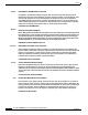
Chapter 1 Cisco SFS 3012R Server Switch Overview Features Figure 1-2 Fully Redundant System Architecture Management workstation Host Controller cards IB switch Host IB switch InfiniBand backplane Ethernet gateway Ethernet switches Fibre Channel gateways 180741 Server Switch Fibre Channel switches The Cisco SFS 3012R Server Switch can be used in a variety of networking environments, including database tiers, application tiers, and Web tiers.
Chapter 1 Cisco SFS 3012R Server Switch Overview Cisco SFS 3012R Server Switch Chassis Cisco SFS 3012R Server Switch Chassis Figure 1-3 displays the back of the Cisco SFS 3012R Server Switch and numbers the slots on the chassis.
Chapter 1 Cisco SFS 3012R Server Switch Overview Cisco SFS 3012R Server Switch Components Figure 1-4 Cisco SFS 3012R Server Switch Chassis, Front View, Bezel Removed 5 3 2 180760 4 1 1 Power supply 4 Power supply (shown empty and covered with blanking panel) 2 Blower module 1 5 System and Blower modules LEDs 3 Blower module 2 Cisco SFS 3012R Server Switch Components The Cisco SFS 3012R Server Switch components support scalability and high availability. They are all field replaceable.
Chapter 1 Cisco SFS 3012R Server Switch Overview Cisco SFS 3012R Server Switch Components Figure 1-5 Cisco SFS 3012R Server Switch Controller Module 4 1 180749 3 2 1 Serial console port 3 Ejector lever 2 Management Ethernet port 4 Controller module LEDs The following points apply to the controller modules: • Each Cisco SFS 3012R Server Switch comes with one active controller and, optionally, one warm standby controller.
Chapter 1 Cisco SFS 3012R Server Switch Overview Cisco SFS 3012R Server Switch Components Ethernet and Fibre Channel Gateways Ethernet and Fibre Channel gateways connect the Cisco SFS 3012R Server Switch and InfiniBand-connected hosts to IP and Fibre Channel networks. All gateways are dual-connected to the redundant InfiniBand backplane of the Cisco SFS 3012R Server Switch. Figure 1-6 displays an Ethernet gateway. Figure 1-7 displays a Fibre Channel gateway.
Chapter 1 Cisco SFS 3012R Server Switch Overview Cisco SFS 3012R Server Switch Components Figure 1-7 Fibre Channel Gateway Expansion Module 4 1 2 180750 3 1 Fibre Channel port 1 3 Ejector handle 2 Fibre Channel port 2 4 Fibre Channel gateway status LEDs Cisco SFS 3012R Multifabric Server Switch Hardware Installation Guide 1-8 OL-11187-01
Chapter 1 Cisco SFS 3012R Server Switch Overview Cisco SFS 3012R Server Switch Components InfiniBand Switch Modules InfiniBand switch modules connect the Cisco SFS 3012R Server Switch to InfiniBand-attached hosts and other switches in the InfiniBand network. The Cisco SFS 3012R Server Switch supports one or two InfiniBand switch modules. The 12-port InfiniBand switch expansion module is shown in Figure 1-8.
Chapter 1 Cisco SFS 3012R Server Switch Overview Cisco SFS 3012R Server Switch Components Power Supply Modules Power supply modules reside in slots on the left-hand side and right-hand side of the front (bezel end) of the Cisco SFS 3012R Server Switch as shown in Figure 1-4. Redundant power supplies support hot swaps. When your server switch includes only one power supply, you can add a second power supply while the chassis runs.
Chapter 1 Cisco SFS 3012R Server Switch Overview Cisco SFS 3012R Server Switch Components Blower Modules The hot-swappable blower modules (fans) of your Cisco SFS 3012R Server Switch maintain the internal temperature of your server switch. You do not need to turn off power to the chassis to replace a blower module. You access the blower module from the front (bezel end) of the Cisco SFS 3012R Server Switch chassis as shown in Figure 1-4.
Chapter 1 Cisco SFS 3012R Server Switch Overview Cisco SFS 3012R Server Switch Components Cisco SFS 3012R Multifabric Server Switch Hardware Installation Guide 1-12 OL-11187-01
C H A P T E R 2 Installing and Booting the Cisco SFS 3012R Server Switch This chapter explains how to mount your Cisco SFS 3012R Server Switch on a rack, boot the Cisco SFS 3012R Server Switch, and configure basic services. For advanced configuration information, refer to the Cisco SFS 7000 Series Product Family Command Reference or the Cisco SFS 7000 Series Product Family Element Manager User Guide.
Chapter 2 Installing and Booting the Cisco SFS 3012R Server Switch Safety Warning This unit is intended for installation in restricted access areas. A restricted access area can be accessed only through the use of a special tool, lock and key, or other means of security. Statement 1017 Warning This equipment must be grounded. Never defeat the ground conductor or operate the equipment in the absence of a suitably installed ground conductor.
Chapter 2 Installing and Booting the Cisco SFS 3012R Server Switch Preparing for Installation Preparing for Installation Warning Two people are required to lift the chassis. Grasp the chassis underneath the lower edge and lift with both hands. To prevent injury, keep your back straight and lift with your legs, not your back.
Chapter 2 Installing and Booting the Cisco SFS 3012R Server Switch Mounting the Cisco SFS 3012R Server Switch on a Rack Mounting the Cisco SFS 3012R Server Switch on a Rack Warning Two people are required to lift the chassis. Grasp the chassis underneath the lower edge and lift with both hands. To prevent injury, keep your back straight and lift with your legs, not your back.
Chapter 2 Installing and Booting the Cisco SFS 3012R Server Switch Mounting the Cisco SFS 3012R Server Switch on a Rack Step 3 Step 4 Attach the shelf rails to either side of the Cisco SFS 3012R Server Switch chassis as follows: a. Unpack the shelf assembly kit (ordered and shipped separately). b. Identify the shelf rails labeled TS360/SFS 3012. c. Attach the rails to the chassis with the four screws provided, as shown in Figure 2-1.
Chapter 2 Installing and Booting the Cisco SFS 3012R Server Switch Mounting the Cisco SFS 3012R Server Switch on a Rack e. Note f. Step 5 Figure 2-3 Secure the shelf end to the post with four screws (not included) that fit your rack, but do not tighten the screws. When you install the shelf assembly, do not fully tighten the screws at the cable end of the shelf.
Chapter 2 Installing and Booting the Cisco SFS 3012R Server Switch Mounting the Cisco SFS 3012R Server Switch on a Rack Step 7 Use 4 standard rack screws (not included) to secure the rack-mounting brackets to the rack posts, as shown in Figure 2-4. Securing the Chassis to the Rack 180736 Figure 2-4 Step 8 Firmly tighten the shelf screws at the cable end.
Chapter 2 Installing and Booting the Cisco SFS 3012R Server Switch Attaching a Serial Console Cable to a PC or Terminal Attaching a Serial Console Cable to a PC or Terminal Step 1 Connect the cable from the serial console port on the controller module to your terminal or management workstation. Use the straight-through M/F serial cable, which is provided in the package. For detailed information about how to connect the serial console cable, see the documentation included with the serial cable kit.
Chapter 2 Installing and Booting the Cisco SFS 3012R Server Switch Booting the Cisco SFS 3012R Server Switch and Configuring Basic Connectivity Assigning a Static IP Address To configure basic Ethernet connectivity with a static IP address, perform the following steps: Step 1 Attach an Ethernet cable (not provided) from the management port to the Ethernet router or switch. Step 2 Enter the enable command. SFS-3012R> enable SFS-3012R# Step 3 Enter the configure command.
Chapter 2 Installing and Booting the Cisco SFS 3012R Server Switch Connecting InfiniBand Hosts Step 4 Enter the interface mgmt-ethernet command. SFS-3012R(config)# interface mgmt-ethernet Step 5 Enter the addr-option dhcp command to configure the chassis to obtain the IP address from the DHCP server. SFS-3012R(config-if-mgmt-ethernet)# addr-option dhcp Step 6 Enable the management port with the no shutdown command.
Chapter 2 Installing and Booting the Cisco SFS 3012R Server Switch Connecting InfiniBand Hosts Figure 2-5 InfiniBand Cable with Pinch Connector 144960 10 Figure 2-6 InfiniBand Cable with Pull Connector 144961 12 Note If your host does not provide enough free space around a given InfiniBand port, verify that your InfiniBand cable connector engages fully. Wiggle your connector back and forth to be sure that both sides of the connector have locked firmly into place.
Chapter 2 Installing and Booting the Cisco SFS 3012R Server Switch Managing the Cisco SFS 3012R Server Switch Removing a Pinch Connector 13 Press here Press here 144962 Figure 2-7 To remove a cable with a pull connector, grasp the connector with one hand and push it toward the port, and then pull the latch away from the port with your other hand and gently wiggle the connector away from the port, as shown in Figure 2-8.
C H A P T E R 3 Installing and Removing Server Switch Field Replaceable Units (FRUs) This chapter provides step-by-step instructions for performing the following procedures: • Installing a Controller Module, page 3-2 • Adding or Replacing Ethernet or Fibre Channel Gateways, page 3-3 • Installing an InfiniBand Switch Module, page 3-4 • Removing an InfiniBand Switch Module, page 3-7 • Installing a Power Supply Module, page 3-7 • Removing a Power Supply Module, page 3-9 • Installing a Blower Mod
Chapter 3 Installing and Removing Server Switch Field Replaceable Units (FRUs) Installing a Controller Module Installing a Controller Module To install a controller module, perform the following steps: Step 1 Ground yourself with an approved ground wrist strap. Step 2 Remove the blanking panel if one resides in the slot. Step 3 Remove the controller module from any packaging. Step 4 Extend the ejector lever on the module completely.
Chapter 3 Installing and Removing Server Switch Field Replaceable Units (FRUs) Adding or Replacing Ethernet or Fibre Channel Gateways Step 7 Push the ejector lever up until it clicks into place, as shown in Figure 3-2. Closing the Ejector Lever 180743 Figure 3-2 Adding or Replacing Ethernet or Fibre Channel Gateways You can add, remove, and swap I/O gateways while your Cisco SFS 3012R Server Switch runs.
Chapter 3 Installing and Removing Server Switch Field Replaceable Units (FRUs) Installing an InfiniBand Switch Module Note You can install gateways in slots 2 (second from left) through 13 (second from right). Populate your Cisco SFS 3012R Server Switch from left to right. Step 6 Push the gateway module firmly into the slot. The ejector lever begins to close. Step 7 Push the ejector lever up until it clicks into place.
Chapter 3 Installing and Removing Server Switch Field Replaceable Units (FRUs) Installing an InfiniBand Switch Module Step 6 Press the switch module firmly into the slot so the fasteners begin to close, as shown in Figure 3-3. Inserting a Switch Module 180768 Figure 3-3 Step 7 Close both fastener levers simultaneously and completely.
Chapter 3 Installing and Removing Server Switch Field Replaceable Units (FRUs) Installing an InfiniBand Switch Module Step 8 Tighten the screws on either side of the switch module to secure it to the chassis. Securing an InfiniBand Switch Module 180744 Figure 3-5 Step 9 Verify that the system image on the InfiniBand switch module is consistent with the image on other cards in the chassis and update the image, if necessary.
Chapter 3 Installing and Removing Server Switch Field Replaceable Units (FRUs) Removing an InfiniBand Switch Module Removing an InfiniBand Switch Module To remove an InfiniBand switch module from the Cisco SFS 3012R Server Switch chassis, perform the following steps: Step 1 Make sure the Cisco SFS 3012R Server Switch chassis is securely seated in the rack. Step 2 If you are removing the InfiniBand module from slot 16 (the lower module), you must power down the chassis before removing the module.
Chapter 3 Installing and Removing Server Switch Field Replaceable Units (FRUs) Installing a Power Supply Module To insert a power supply, perform the following steps: Step 1 Ground yourself using an approved ground wrist strap. Step 2 Remove the blanking panel if one resides in the slot. Step 3 Remove the power supply module from any packaging. Step 4 Insert the power supply into an open slot such that the pull handle sits toward the outside of the chassis, away from the blower module.
Chapter 3 Installing and Removing Server Switch Field Replaceable Units (FRUs) Removing a Power Supply Module Removing a Power Supply Module Caution Never place your hand inside an empty module bay or anywhere inside the Cisco SFS 3012R Server Switch. To remove the power supply, perform the following steps: Step 1 Ground yourself using an approved ground wrist strap. Step 2 Remove the power cord from the power supply. Step 3 Disengage the power supply by pulling it toward you.
Chapter 3 Installing and Removing Server Switch Field Replaceable Units (FRUs) Installing a Blower Module Step 3 Insert the blower module into an open slot until it is fully seated so that the captive screw sits at the top of the module, as shown in Figure 3-6. Inserting a Power Supply 180763 Figure 3-6 Step 4 Tighten the captive screw on the front panel to secure the module to the chassis, as shown in Figure 3-7.
Chapter 3 Installing and Removing Server Switch Field Replaceable Units (FRUs) Removing a Blower Module Removing a Blower Module To remove a blower module, perform the following steps: Step 1 Ground yourself using an approved ground wrist strap. Step 2 Unfasten the captive screw. Step 3 Pull the blower module toward you until it completely disengages from the chassis. Step 4 Insert a replacement blower module into the empty chassis bay to ensure appropriate cooling.
Chapter 3 Installing and Removing Server Switch Field Replaceable Units (FRUs) Removing a Blower Module Cisco SFS 3012R Multifabric Server Switch Hardware Installation Guide 3-12 OL-11187-01
C H A P T E R 4 Viewing and Updating the Software Image Sections in this chapter provide instructions on the following procedures: • Viewing the Software Image Version, page 4-1 • Updating the Software Image, page 4-4 • Deleting a Software Image, page 4-9 You can update the software image on all cards in the chassis at once, or on individual cards.
Chapter 4 Viewing and Updating the Software Image Viewing the Software Image Version Viewing the Software Image Version with the CLI Use the CLI to view software versions on the chassis as follows: Step 1 To view the primary software image version for all cards in the chassis, use the show card-inventory command, as shown in the following example: SFS-3012R# show card-inventory ================================================================================ Card Resource/Inventory Information ==========
Chapter 4 Viewing and Updating the Software Image Viewing the Software Image Version 1 Tue Nov 25 19:34:08 2003 19228160 TopspinOS-2.0.0/build211 1 Tue Nov 25 19:32:16 2003 15539200 TopspinOS-2.0.0/build212 SFS-3012R# Interpret the display as follows: a. Identify files that have been installed and the files that have been downloaded but not installed: – A .img file is an image file that is not installed. – An installed image file has a slash (/) in the name. b.
Chapter 4 Viewing and Updating the Software Image Updating the Software Image Step 3 View the software version on individual cards in the chassis: a. Double-click on any module in the main GUI. b. Click the Inventory tab. The properties window appears for that module, as shown in Figure 4-2. Figure 4-2 c. Viewing Current Image of an Individual Module View the Current Image Source field.
Chapter 4 Viewing and Updating the Software Image Updating the Software Image Updating the Software Image with the CLI Use the CLI to update the software image as follows: Step 1 Copy the image to the chassis controller. Note Perform this step only if the .img file containing the desired software image is not already on the controller.
Chapter 4 Viewing and Updating the Software Image Updating the Software Image b. Enter boot-config primary-image-source, and then paste the copied image file name, as shown in the following example: SFS-3012R# configure SFS-3012R(config)# boot-config primary-image-source TopspinOS-2.1.0/build497 SFS-3012R(config)# exit Step 4 Reboot the chassis using the reload command.
Chapter 4 Viewing and Updating the Software Image Updating the Software Image Step 3 Click the Import button. The Import File window appears. Figure 4-3 Copying an Image File to the Server Switch a. Select Image from the File Type drop-down menu. b. Click the Remote FTP Sever radio button from the Copy From section (or click the Remote SCP Server radio button if you will download from an SCP server). c.
Chapter 4 Viewing and Updating the Software Image Updating the Software Image Step 4 Click the Copy button to copy the file onto the controller of the sever switch. Wait until the transfer is complete. The window will automatically refresh to show the latest copied image file. Step 5 Activate the image. After downloading the image file to the chassis controller, it must be installed to become active. Before activating the image, ensure that the following conditions are true: • The file name has the .
Chapter 4 Viewing and Updating the Software Image Deleting a Software Image b. Click yes in the Save changes to the system configuration dialog box. c. Click Ok in the The chassis will now be rebooted dialog box. Deleting a Software Image The following files are candidates for deletion through either the CLI or the Element Manager: • .img files. A .img file is an image file that is not installed.
Chapter 4 Viewing and Updating the Software Image Deleting a Software Image Deleting an Image with the Element Manager GUI Delete a software image with Element Manager as follows: Step 1 Select Maintenance > File Management. Step 2 Click on the .img file that you want to delete, as shown in Figure 4-5. Figure 4-5 Deleting an Image File Step 3 Click the Delete button. Step 4 Click Yes in the Delete file? dialog box.
C H A P T E R 5 Cisco SFS 3012R Server Switch LEDs The following sections appear in this chapter: • Cisco SFS 3012R Server Switch System Status LED, page 5-2 • Power Supply LEDs, page 5-3 • Blower Module LEDs, page 5-4 • Controller LEDs, page 5-5 • InfiniBand LEDs, page 5-7 • Fibre Channel LEDs, page 5-9 • Ethernet Gateway LEDs, page 5-11 LEDs on your Cisco SFS 3012R Server Switch and installed components indicate hardware status.
Chapter 5 Cisco SFS 3012R Server Switch LEDs Cisco SFS 3012R Server Switch System Status LED Cisco SFS 3012R Server Switch System Status LED The Cisco SFS 3012R Server Switch system status LED appears on the top-left corner of the front (bezel end) of the server switch. You can view the system status LED with the bezel on or off, as shown in Figure 5-1. Table 5-1 describes system status LED indications.
Chapter 5 Cisco SFS 3012R Server Switch LEDs Power Supply LEDs Power Supply LEDs Power supply status LEDs are located above and below the pull handle, as shown in Figure 5-2. Table 5-2 and Table 5-3 interpret the power supply LEDs. Figure 5-2 Power Supply LEDs 180765 1 2 1 2 DC power supply LED Table 5-2 AC Power Supply LED LED State Indication Solid green AC input present. Off AC input absent.
Chapter 5 Cisco SFS 3012R Server Switch LEDs Blower Module LEDs Blower Module LEDs Blower module LEDs are located immediately to the left of the system status LED on the bezel end of the Cisco SFS 3012R Server Switch as shown in Figure 5-3. Each blower LED is a dual-color green/yellow LED. Table 5-4 explains Blower module LED indications. Figure 5-3 Blower Module LEDs 1 180757 2 1 Blower 1 (the right blower) status LED Table 5-4 2 Blower 2 (the left blower) status LED.
Chapter 5 Cisco SFS 3012R Server Switch LEDs Controller LEDs Controller LEDs Controller modules include module status LEDs as well as Management Ethernet port LEDs. The controller LEDs are shown in Figure 5-4 and described in the callout table below it. Table 5-5, Table 5-6, and Table 5-7 interpret the controller module status LEDs.
Chapter 5 Cisco SFS 3012R Server Switch LEDs Controller LEDs Table 5-7 Power Status LEDs Power LED States Indication Green on, yellow off Power supplies run with no errors. Green off, yellow on Power supplies have a problem that requires user intervention. See Power supply LEDs on the front of the chassis for additional details. Green off, yellow off No power to the chassis. Figure 5-5 shows the location of the Management Ethernet port LEDs. Table 5-8 explains the LEDs.
Chapter 5 Cisco SFS 3012R Server Switch LEDs InfiniBand LEDs InfiniBand LEDs Each InfiniBand switch module includes two LEDs that provide status about the module itself and LEDs that provide information about each InfiniBand port, as shown in Figure 5-6.
Chapter 5 Cisco SFS 3012R Server Switch LEDs InfiniBand LEDs InfiniBand Port LEDs Two port LEDs (both green) appear next to each InfiniBand port on the switch module, as shown in Figure 5-6. Both the top and bottom InfiniBand port LEDs are solid green. The top LED indicates a logical link has taken place. (A logical link is established when the subnet manager makes a sweep. A logical link must be established if you are to use the port.) The bottom LED indicates a physical link has occurred.
Chapter 5 Cisco SFS 3012R Server Switch LEDs Fibre Channel LEDs Fibre Channel LEDs The location of the Fibre Channel gateway LEDs and Fibre Channel port LEDs for port 1 are shown in Figure 5-7.
Chapter 5 Cisco SFS 3012R Server Switch LEDs Fibre Channel LEDs Fibre Channel Port LEDs Fibre Channel Port LEDs are adjacent to each Fibre Channel port. They indicate port status and activity. Each port has a one bi-color, green/yellow, LED to indicate port status.
Chapter 5 Cisco SFS 3012R Server Switch LEDs Ethernet Gateway LEDs Ethernet Gateway LEDs Figure 5-8 shows the location of the Ethernet gateway LEDs and the Ethernet port LEDs. Figure 5-8 Location of Ethernet Gateway and Ethernet Port LEDs 1 2 3 180756 4 1 Ethernet gateway LED (yellow) 3 Ethernet port status LED 2 Ethernet gateway LED (green) 4 Ethernet port activity LED The Ethernet gateway provides one yellow LED and one green LED.
Chapter 5 Cisco SFS 3012R Server Switch LEDs Ethernet Gateway LEDs Ethernet Gateway LEDs Table 5-14 Ethernet Gateway LED Indications LED States Indication Yellow on, green off Auxiliary power has reached the gateway. Green on, yellow off Gateway runs successfully. Green on, yellow on An error has occurred. Ethernet Port LEDs Ethernet port LEDs are located on the Ethernet ports. Figure 5-8 shows the location of the Ethernet port LEDs for one port.
A P P E N D I X A Specifications and Compliance This appendix details the Cisco SFS 3012R Server Switch specifications and compliance certifications. General Specifications Table A-1 General Specifications Specification Detail Operating Temperature Range 0 to 35°C Non-Operating Temperature Range -40 to 65 °C Operating Temperature Gradient 20°C maximum per 60 min Operating Altitude 0 - 10,000 ft Non-Operating Alt.
Appendix A Specifications and Compliance Electrical Specifications Electrical Specifications Table A-2 Electrical Specifications Category Specification AC Power Auto-ranging 90-264VAC, 47-63Hz. Dual independent IEC connectors, left and right justified. Power Dissipation < 650 W maximum Certifications/Regulatory Table A-3 Certifications/Regulatory Certifications EMC: Class A Radiated and Conducted Emissions per FCC Part 15, subpart B (USA) and ICES-003 (Canada) Safety: UL60950, 3rd ed.
I N D EX controller modules A features of architecture audience 1-2 installing vii LEDs 1-5 3-2 to 3-3 5-5 location of 1-4 slot numbers for B basic connectivity 2-8 D blower modules features of installing LEDs 1-11 DHCP 3-9 to 3-10 2-9 dir image command 5-4 1-5 removing cisco.
Index F Fibre Channel gateways features of installing LEDs 1-7 to 1-8 port LEDs 5-8 3-7 slot numbers for 3-3 to 3-4 1-4 verifying software for install command Fibre Channel port LEDs 5-10 xvii 3-6 4-5 installing the chassis in a rack 2-4 IP address field replaceable units features of 1-4 removing 5-9 field notices location of dynamic 1-5 to 1-11 installing 3-1 to 3-11 removing 3-1 to 3-11 static FRU.
Index R racking the chassis 2-4 rack shelf, assembling and installing redundancy 2-5 1-2 related manuals xiv S safety information scalability ix to xiv, 2-1 1-3 security, reporting problems serial console xvi 2-8 serial console cable 2-8 service requests severity, definitions of submitting xviii xviii shelf, assembling and installing show card command 2-5 3-6 show card inventory command 4-2 slot numbers, location and use 1-4 software image deleting with CLI 4-9 deleting with Elem
Index Cisco SFS 3012R Multifabric Server Switch Hardware Installation Guide IN-4 OL-11187-01