Cisco Video Surveillance 7030 IP Camera Installation Guide Americas Headquarters Cisco Systems, Inc. 170 West Tasman Drive San Jose, CA 95134-1706 USA http://www.cisco.
NOTICE. ALL STATEMENTS, INFORMATION, AND RECOMMENDATIONS IN THIS MANUAL ARE BELIEVED TO BE ACCURATE BUT ARE PRESENTED WITHOUT WARRANTY OF ANY KIND, EXPRESS OR IMPLIED. USERS MUST TAKE FULL RESPONSIBILITY FOR THEIR APPLICATION OF ANY PRODUCTS. THE SOFTWARE LICENSE AND LIMITED WARRANTY FOR THE ACCOMPANYING PRODUCT ARE SET FORTH IN THE INFORMATION PACKET THAT SHIPPED WITH THE PRODUCT AND ARE INCORPORATED HEREIN BY THIS REFERENCE.
CONTENTS Preface v Overview v Organization v Obtaining Documentation, Obtaining Support, and Security Guidelines CHAPTER 1 Overview 1-1 Introduction 1-1 Package Contents 1-2 IP Camera Physical Details 1-3 General Purpose I/O Terminal Block CHAPTER 2 v Camera Installation 1-5 2-1 Installation Guidelines 2-1 Warnings Before Installation 2-1 Installing the IP Camera with a Vandal Resistant Enclosure CHAPTER 3 Performing the Initial Setup of the IP Camera CHAPTER 4 Camera Manag
Contents Cisco Video Surveillance 7030 IP Camera Installation Guide iv OL-28692-01
Preface Overview This document, Cisco Video Surveillance 7030 IP Camera Installation Guide, provides information about installing and deploying the Cisco Video Surveillance 7030 IP Camera. Organization This manual is organized as follows: Chapter 1, “Overview” Provides an overview of the IP camera and its features. Chapter 2, “Camera Installation” Provides instructions for physically installing the IP camera.
Preface Cisco Video Surveillance 7030 IP Camera Installation Guide vi OL-28692-01
CH A P T E R 1 Overview This chapter describes the Cisco Video Surveillance 7030 IP Camera, and includes the following topics: • Introduction, page 1-1 • Package Contents, page 1-2 • IP Camera Physical Details, page 1-3 Introduction The Cisco Video Surveillance 7030 IP camera is an outdoor, high definition, professional fixed dome IP camera with industry-leading image quality and processing power.
Chapter 1 Overview Package Contents Package Contents The Cisco Video Surveillance IP Camera package includes the following items: • Cisco Video Surveillance 7030 IP Camera (1) • Installation template and alignment sticker (1) • Mounting plate (1) • Black cover (1) • Bushing (1) • Waterproof connector (1) • L type hex key (allen wrench) (1) • Screws (t4x32) (4) • Wall anchors (4) • Hex nut (1) • Double sided tape (1) • Silica gel (1) • Extra set of labels (3) • Cisco documentati
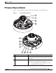
Chapter 1 Overview IP Camera Physical Details IP Camera Physical Details Figure 1-1 and the table that follows describe the physical features of the 7030 IP camera. Figure 1-1 IP Camera Physical Features 1 2 3 4 5 6 7 8 9 10 11 12 1 Varifocal lens IP camera lens that changes focus as the focal length changes. 2 IR LEDs Infrared illuminator LEDs that enhance the video image (effective up to 60 ft. [20 m]) when the IP camera is running in night mode.
Chapter 1 Overview IP Camera Physical Details 4 Tilt adjustment screw Used when tilting the camera to set the field of view. 5 Light sensor Senses the level of ambient light to determine when to switch day/night mode. 6 Recessed reset button Recessed button that reboots the IP camera or resets it to a default state. You can use a pin or paper clip to depress it.
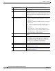
Chapter 1 Overview General Purpose I/O Terminal Block General Purpose I/O Terminal Block Figure 1-2 shows the GPIO terminal block pin locations and descriptions. Figure 1-2 GPIO Terminal Block Pin Locations and Descriptions 1 2 3 4 5 6 7 8 Note Pin Description 1 24 VAC 2 24 VAC 3 DI- 4 DI3+ 5 DI2+ 6 DI1+ 7 DO- 8 DO+ The maximum output load from pins 7 and 8 is 50mA.
Chapter 1 Overview General Purpose I/O Terminal Block Cisco Video Surveillance 7030 IP Camera Installation Guide 1-6 OL-28692-01
CH A P T E R 2 Camera Installation This chapter provides information and instructions for installing the Cisco Video Surveillance 7030 IP Camera, and includes the following topics: • Installation Guidelines, page 2-1 • Warnings Before Installation, page 2-1 • Installing the IP Camera with a Vandal Resistant Enclosure, page 2-4 Installation Guidelines This section describes how to install the IP camera.
Chapter 2 Camera Installation Warnings Before Installation • Do not place the IP Camera around heat sources, such as a television or oven. • Refer to your user’s manual for the operating temperature. • Keep the IP Camera away from direct sunlight. • Do not place the IP Camera in high humidity environments. • Do not place the IP Camera on unsteady surfaces. • Do not touch the IP Camera during a lightning storm.
Chapter 2 Camera Installation Warnings Before Installation • Do not disassemble the IP Camera. • Do not insert sharp or tiny objects into the IP Camera. • Do not drop the IP Camera. Warning Installation of the equipment must comply with local and national electrical codes. Statement 1074 Warning The power supply must be placed indoors. Statement 331 Note If you use the IP camera outdoors, place the camera and the power supply in a suitable NEMA enclosure.
Chapter 2 Camera Installation Installing the IP Camera with a Vandal Resistant Enclosure Note The equipment is to be connected to a Listed class 2, limited power source. Installing the IP Camera with a Vandal Resistant Enclosure To install the IP camera to a ceiling or wall using a vandal resistant (VR) enclosure, perform the following steps. Procedure Step 1 Attach the included alignment sticker to the ceiling or wall.
Chapter 2 Camera Installation Installing the IP Camera with a Vandal Resistant Enclosure Step 5 Note Perform the following steps to install and connect an RJ45 Ethernet cable. We recommended using 24AWG (0.51 mm) gauge cable. a. Drill a hole on the rubber seal plug and insert an Ethernet cable (without a connector) through the opening. b. Strip about 1/2 inch (12 mm) of the sheath from the Ethernet cable. c. Use an RJ45 crimping tool to attach the Ethernet wires to a connector.
Chapter 2 Camera Installation Installing the IP Camera with a Vandal Resistant Enclosure d. Step 6 Press the Ethernet cable into the routing path at the bottom of the camera so that the cable will not get in the way when the metal mounting plate is attached. (Optional) Perform the following steps to install and connect an external power cable and I/O cables for external devices: a. Disassemble the components of the waterproof connector into parts (A) ~ (F).
Chapter 2 Camera Installation Installing the IP Camera with a Vandal Resistant Enclosure c. Feed the power cable through the waterproof connector (F --> E --> D --> B --> A). Be sure to feed enough power cable length through the waterproof connector to connect the power cable to the GPIO block. (A) (B) (D) (E) (F) Note d. There are 8 holes on the seal (D), and the widest holes with a crack on the side are specific for power cables.
Chapter 2 Camera Installation Installing the IP Camera with a Vandal Resistant Enclosure Step 7 Use the included L-type wrench to secure the conduit base to the mounting plate with the three included screws. Step 8 (Optional) Use mini cable with BNC connector to temporarily attach an NTSC or PAL compliant analog video display device to the analog video out port on the rear of the IP camera.
Chapter 2 Camera Installation Installing the IP Camera with a Vandal Resistant Enclosure c. Rotate the IP camera to adjust the horizontal orientation until you achieve a level image. Step 10 (Optional) If the IP camera is installed in a high humidity environment, remove the wrapper from the included silica gel pack and place the pack with the camera inside the VR housing. Ensure that the silica gel pack does not obstruct the IP camera field of view.
Chapter 2 Camera Installation Installing the IP Camera with a Vandal Resistant Enclosure • After completing the initial setup, use the IP camera user interface to adjust the focal length and zoom factor. For more information, see the “Adjusting the IP Camera Focus and Zoom” section on page 4-3.
CH A P T E R 3 Performing the Initial Setup of the IP Camera After you install IP camera as described in the Chapter 2, “Camera Installation,” or after you perform a factory reset procedure, you must access the IP camera and make initial configuration settings. These settings include administrator and root passwords, and whether the IP camera can be accessed through an HTTP connection in addition to the default HTTPS (HTTP secure) connection.
Chapter 3 Step 3 Performing the Initial Setup of the IP Camera In the Password and Confirm Password fields of the admin row, enter a password for the IP camera administrator. You must enter the same password in both fields. The password is case sensitive and must contain at least eight characters, which can be letters, numbers, and special characters, but no spaces. Special characters are: ! " # $ % & ' ( ) * + , - . : ; < = > ? @ [ \ ] ^ _ ` { | } ~.
CH A P T E R 4 Camera Management This chapter provides information and instructions for managing the Cisco Video Surveillance 2620 IP Camera, and includes the following topics: • Understanding the IP Camera User Interface, page 4-1 • Adjusting the IP Camera Focus and Zoom, page 4-3 • Powering the IP Camera On or Off, page 4-4 • Resetting the IP Camera, page 4-4 • Viewing Live Video, page 4-5 Understanding the IP Camera User Interface After you log in to the IP camera, you can access the IP camer
Chapter 4 Camera Management Understanding the IP Camera User Interface Table 4-1 Links in the IP Camera Windows (continued) Link Description Privilege Level View Video Displays the Camera Video & Control window. Administrator You may be prompted to install ActiveX controls when trying to User access this window for the first time. ActiveX controls are required to view video from the IP camera. Follow the on-screen prompts to install ActiveX controls.
Chapter 4 Camera Management Adjusting the IP Camera Focus and Zoom Table 4-2 Home Window Information (continued) Field Description Gateway Address IP address of the gateway through which the IP camera is connected. Primary DNS IP address of the primary DNS server, if configured for the IP camera. Secondary DNS IP address of the secondary DNS server, if configured for the IP camera. IO Port Status Input Port 1 Current state of input port 1 on the IP camera.
Chapter 4 Camera Management Powering the IP Camera On or Off Step 7 (Optional) Click Auto Focus to have the IP camera automatically adjust its focus. To automatically adjust the focus to a particular region in the field of view, check the Specify Region check box and draw or select a region before clicking Auto Focus. Powering the IP Camera On or Off The IP camera does not include an on/off switch. You power it on or off by connecting it to or disconnecting it from a power source.
Chapter 4 Camera Management Viewing Live Video Viewing Live Video After you install and set up the Cisco Video Surveillance IP Camera, you can connect to the IP camera through Internet Explorer and access the Camera Video & Control window to view live video. The Camera Video & Control window also provides for controlling the video display, configuring preset positions, and controlling certain IP camera functions. Available controls depend on the privilege level of the user.
Chapter 4 Camera Management Viewing Live Video Table 4-4 Camera Video & Control Window Controls (continued) Control Description Contrast slider To control contrast of the video image, drag the slider, or enter a value from 1 through 10 and press the Enter key. A higher value increases the contrast and a lower value decreases the contrast. The default value is 5.
Chapter 4 Camera Management Viewing Live Video Table 4-4 Camera Video & Control Window Controls (continued) Control Description Restore button Displays the default video image, which is not rotated and not reversed. Full Screen button Displays the video image in full screen mode. To return to normal display mode, click the full screen image. Motion detection Up Arrow toggle button Down Arrow toggle button Click the Up Arrow to display the motion detection controls.
Chapter 4 Camera Management Viewing Live Video Table 4-4 Camera Video & Control Window Controls (continued) Control Description Full Screen check box Becomes available when you click check Enable Motion Detection check box. Check the Full Screen check box to cause the IP camera to examine the entire video field for activity.
INDEX A G About link GPIO terminal block 4-2 ActiveX controls 2-7 4-2 H B help, for IP camera windows brightness 4-2 Home window 4-5 description displaying C 4-2 4-1 HTTP, allowing access through 3-2 camera See IP camera I Camera Video/Control window accessing description displaying installing 4-5 GPIO terminal block 4-2 IP camera 4-2 connecting, to the IP camera for the first time contrast 2-1 mounting to ceiling or wall warnings 3-1 PC requirements for 2-7 2-1 waterproo
Index powering off 4-4 powering on 4-4 tilting R rebooting, IP camera 4-6 windows Refresh link 4-2 4-4 4-1 reset factory default values L reboot 4-4 4-4 live video viewing S through home window 4-5 through third-party device or software 4-5 saturation 4-6 sensitivity, for motion detection See also video log out, of IP camera 4-7, 4-8 Setup window 4-2 description displaying M sharpness 4-2 4-2 4-6 motion detection accessing controls controls 4-7 enabling 4-7 sensitivit
Index W warnings before installation waterproof connector 2-1 2-6 Z zoom accessing controls zoom controls 4-8 4-8 Cisco Video Surveillance 7030 IP Camera Installation Guide OL-28692-01 IN-3
Index Cisco Video Surveillance 7030 IP Camera Installation Guide IN-4 OL-28692-01