Cisco Video Surveillance 6400 IP Camera Installation Guide Americas Headquarters Cisco Systems, Inc. 170 West Tasman Drive San Jose, CA 95134-1706 USA http://www.cisco.
THE SPECIFICATIONS AND INFORMATION REGARDING THE PRODUCTS IN THIS MANUAL ARE SUBJECT TO CHANGE WITHOUT NOTICE. ALL STATEMENTS, INFORMATION, AND RECOMMENDATIONS IN THIS MANUAL ARE BELIEVED TO BE ACCURATE BUT ARE PRESENTED WITHOUT WARRANTY OF ANY KIND, EXPRESS OR IMPLIED. USERS MUST TAKE FULL RESPONSIBILITY FOR THEIR APPLICATION OF ANY PRODUCTS.
INDEX Preface INDEX v Overview v Organization v Obtaining Documentation, Obtaining Support, and Security Guidelines CHAPTER 1 Overview 1-1 Introduction 1-1 Package Contents 1-2 IP Camera Physical Details 1-2 Front View 1-2 Back View 1-3 General Purpose I/O Terminal Block CHAPTER 2 v Camera Installation 1-4 2-1 Installation Guidelines 2-1 Warnings Before Installation Installing the IP Camera 2-2 2-3 Connecting External Power and I/O Cables Connecting a Waterproof Ethernet Cable I
Contents INDEX Cisco Video Surveillance 6400 IP Camera Installation Guide iv OL-28494-01
Preface Overview This document, Cisco Video Surveillance 6400 IP Camera Installation Guide, provides information about installing and deploying the Cisco Video Surveillance 6400 High-Definition IP Camera. Organization This manual is organized as follows: Chapter 1, “Overview” Provides an overview of the IP camera and its features. Chapter 2, “Camera Installation” Provides instructions for physically installing the IP camera.
Preface Cisco Video Surveillance 6400 IP Camera Installation Guide vi OL-28494-01
CH A P T E R 1 Overview This chapter describes the Cisco Video Surveillance 6400 High-Definition IP Camera, and includes the following topics: • Introduction, page 1-1 • Package Contents, page 1-2 • IP Camera Physical Details, page 1-2 Introduction The Cisco Video Surveillance 6400 IP camera offers 1080p HD resolution with superb image quality.
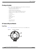
Chapter 1 Overview Package Contents Package Contents The Cisco Video Surveillance 6400 IP Camera package includes the following items: • Cisco Video Surveillance 6400 IP camera (1) • Mounting plate alignment sticker (1) • Wall mount bracket with mounting plate (1) • Waterproof connector assembly for RJ45 Ethernet enclosure (1) • Waterproof connector assembly for power and I/O cables (1) • Sun shield(1) • Standoff screws (2) • Screws (6) • Double sided tape (1) • Silica gel (1) • Pad
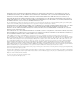
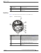
Chapter 1 Overview IP Camera Physical Details 1 Single reflector illuminator LEDs (SRLEDs) IR LEDs that enhance the video image when the IP camera is running in night mode. 2 Varifocal lens IP camera lens that changes focus as the focal length changes. 3 Light sensor Senses the level of ambient light to determine when to switch day/night mode. Back View Figure 1-2 and the table that follows describe the back view of the 6400 IP camera.
Chapter 1 Overview IP Camera Physical Details 5 6 Reset button Reboots the IP camera or resets it to a default state. Depending on how long you depress the reset button, you can do either of the following: Audio/Video out (green) • Reset—Press and release the reset button. Wait for the IP Camera to reboot. • Restore—Press and hold the reset button for about 30 seconds. All settings will be restored to factory default. Allows the connection of an optional Y cable or mini cable with BNC connector.
CH A P T E R 2 Camera Installation This chapter provides information and instructions for installing the Cisco Video Surveillance 6400 IP Camera, and includes the following topics: • Installation Guidelines, page 2-1 • Warnings Before Installation, page 2-2 • Installing the IP Camera, page 2-3 • Connecting External Power and I/O Cables, page 2-5 • Connecting a Waterproof Ethernet Cable, page 2-8 • Installing the Sun Shield, page 2-9 Installation Guidelines This section describes how to install
Chapter 2 Camera Installation Warnings Before Installation Warnings Before Installation • Power off the Network Camera as soon as smoke or unusual odors are detected. • Refer to your user's manual for the operating temperature. Contact your distributor in the event of this happening. • Do not place the Network Camera on unsteady surfaces. • Do not touch the Network Camera during a lightning storm. • Do not insert sharp or tiny objects into the Network Camera. • Do not drop the Network Camera.
Chapter 2 Camera Installation Installing the IP Camera Warning This product must be connected to a power-over-ethernet (PoE) IEEE 802.3af compliant power source or an IEC60950 compliant limited power source. Statement 353 Caution Inline power circuits provide current through the communication cable. Use the Cisco provided cable or a minimum 24AWG communication cable. Note The power adapter that you use with the IP camera must provide power that is within +/–10% of the required power.
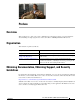
Chapter 2 Camera Installation Installing the IP Camera Step 12 (Optional) If the camera is being install in an area of high humidity, remove the back cover from the camera, place the included silica gel packet in the camera, and then replace the back cover onto the camera.
Chapter 2 Camera Installation Connecting External Power and I/O Cables Connecting External Power and I/O Cables The 6400 IP camera can be powered using Power over Ethernet (PoE), or by using an external power source. If an external power source is used, a power cable must be connected to the General Purpose I/O (GPIO) terminal block on the IP camera. Additionally, external devices that trigger alarms or respond to alarms can be connected to the GPIO terminal block using I/O cables.
Chapter 2 Camera Installation Connecting External Power and I/O Cables Step 4 Feed the external power cable and I/O cables through the wall mount bracket and the waterproof connector components (E –> D –> B –> A). Be sure to feed enough cable length through the waterproof connector to connect the cables to the GPIO terminal block. (A) (B) (D) (E) 4 Note There are seven holes on the seal (B), and the widest hole with a crack on the side is specific for the power cable.
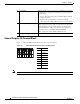
Chapter 2 Camera Installation Connecting External Power and I/O Cables Step 6 Secure the sealing nut (E) tightly. (E) Step 7 Connect the external power and I/O cables to the GPIO terminal block. The pin locations and descriptions are as follows: Pin 1 2 3 4 5 6 7 8 Step 8 1 2 3 4 5 6 7 8 Description 12 VDC12 VDC+ 24 VAC 24 VAC DIDI+ DODO+ Replace the back cover back onto the camera.
Chapter 2 Camera Installation Connecting a Waterproof Ethernet Cable Connecting a Waterproof Ethernet Cable To connect the 6400 IP camera to an Ethernet cable with a waterproof connection, perform the following steps. Procedure Step 1 Disassemble the components of the waterproof connector into its individual components as shown below. Sealing Nut (A) Seal (B) Screw Nut (C) Housing (D) Gasket (E) Step 2 Strip about 1/2 inch (12 mm) of the sheath off the end of an Ethernet cable. 1/2 in.
Chapter 2 Camera Installation Installing the Sun Shield Step 7 Push the RJ45 plug into the housing (D) and tighten the sealing nut. Step 8 Attach the gasket to the front surface of the housing (D). (E) Step 9 Connect the Ethernet cable to the RJ45 jack and tighten the waterproof connector. Installing the Sun Shield To install the sun shield, perform the following steps. Procedure Step 1 Attach the two included standoff screws to the top of the 6400 IP camera.
Chapter 2 Camera Installation Installing the Sun Shield Step 2 Place the sun shield on top of the two standoff screws and slide it backward or forward to the desired position. Ensure that the holes in the top of the standoff screws are visible through the holes in the sun shield. Step 3 Use the two included screws to secure the sun shield to the two standoff screws.
CH A P T E R 3 Performing the Initial Setup of the IP Camera After you install IP camera as described in the Chapter 2, “Camera Installation,” or after you perform a factory reset procedure, you must access the IP camera and make initial configuration settings. These settings include administrator and root passwords, and whether the IP camera can be accessed through an HTTP connection in addition to the default HTTPS (HTTP secure) connection.
Chapter 3 Step 3 Performing the Initial Setup of the IP Camera In the Password and Confirm Password fields of the admin row, enter a password for the IP camera administrator. You must enter the same password in both fields. The password is case sensitive and must contain at least eight characters, which can be letters, numbers, and special characters, but no spaces. Special characters are: ! " # $ % & ' ( ) * + , - . : ; < = > ? @ [ \ ] ^ _ ` { | } ~.
CH A P T E R 4 Camera Management This chapter provides information and instructions for managing the Cisco Video Surveillance 2620 IP Camera, and includes the following topics: • Understanding the IP Camera User Interface, page 4-1 • Adjusting the IP Camera Focus and Zoom, page 4-4 • Powering the IP Camera On or Off, page 4-4 • Resetting the IP Camera, page 4-4 • Viewing Live Video, page 4-5 Understanding the IP Camera User Interface After you log in to the IP camera, you can access the IP camer
Chapter 4 Camera Management Understanding the IP Camera User Interface Table 4-1 Links in the IP Camera Windows (continued) Link Description Privilege Level View Video Displays the Camera Video & Control window. Administrator You may be prompted to install ActiveX controls when trying to User access this window for the first time. ActiveX controls are required to view video from the IP camera. Follow the on-screen prompts to install ActiveX controls.
Chapter 4 Camera Management Understanding the IP Camera User Interface Table 4-2 Home Window Information Field Description General Information ID Identifier of the IP camera. Name Name of the IP camera. Current Time Current date and time of the IP camera. S/N Serial number of the IP camera. Firmware Version of the firmware that is installed on the IP camera. Codec Version of the codec that is running on the IP camera. Part Number Cisco manufacturing part number of the IP camera.
Chapter 4 Camera Management Adjusting the IP Camera Focus and Zoom Adjusting the IP Camera Focus and Zoom To adjust the IP camera focus and zoom, perform the following steps while viewing video from the camera. For information about viewing video, see “Viewing Live Video” section on page 4-5. Procedure Step 1 Login to the IP camera. The Home window appears. Step 2 Click the View Video link. The Camera Video & Control window appears. Step 3 Verify that the field of view is correctly set.
Chapter 4 Camera Management Viewing Live Video You also can also perform these reset operations from the Maintenance Settings window as described in the Cisco Video Surveillance 6000 Series IP Camera Configuration Guide. Table 4-3 Resetting the IP Camera Reset Type Procedure Remarks Reboot. Press and immediately release the Reset button. This action is equivalent to powering the IP camera down and then powering it up. Settings that are configured for the IP camera are retained. Factory reset.
Chapter 4 Camera Management Viewing Live Video Table 4-4 Camera Video & Control Window Controls (continued) Control Description Video Resolution drop-down list Choose the resolution for video transmission. The resolutions in this drop-down list depend on the video standard that you selected. The default value for H.264 is 1920 x 1080. The default value for MJPEG is 1024 x 576. You cannot configure a secondary stream if you configure this resolution for 1920 x 1080.
Chapter 4 Camera Management Viewing Live Video Table 4-4 Camera Video & Control Window Controls (continued) Control Description Image tools Hotspot Zoom button Click this latch button to enables the digital zoom feature, which provides five-step digital zooming in for the normal (not full screen) video display. Click this button again to disable the digital zoom feature. To perform a digital zoom, engage the Hotspot Zoom button and click the video display. The first five clicks zoom the display.
Chapter 4 Camera Management Viewing Live Video Table 4-4 Camera Video & Control Window Controls (continued) Control Description Motion detection controls Note These controls appear when you click the Up Arrow in the Motion Detection area and are available only viewing the primary (H.264) stream. Enable Motion Detection check box Enables the motion detection feature and displays a grid over the video image.
Chapter 4 Camera Management Viewing Live Video Table 4-4 Camera Video & Control Window Controls (continued) Control Description Restore button Deselects all areas in the video field that you have selected for motion detection monitoring. Save Settings button Save the current motion detection configuration.
Chapter 4 Camera Management Viewing Live Video Cisco Video Surveillance 6400 IP Camera Installation Guide 4-10 OL-28494-01
INDEX Home window A description About link 4-2 4-2 displaying ActiveX controls 4-2 4-1 HTTP allowing access through 3-2 B brightness I 4-6 installing IP camera C 2-1 IP address default for IP camera camera obtaining from DCHP server See IP camera displaying accessing through a web browser 4-5 description connecting to for the first time 4-2 installation 4-2 PC requirements for contrast panning 3-1 3-1 4-6 4-7 4-4 powering on 4-4 4-7 windows D DHCP, obtaining IP address
Index M T motion detection threshold, for motion detection accessing controls enabling tilting 4-7 4-8 4-7 4-8 sensitivity 4-8 threshold V 4-8 Motion detection controls 4-8 video viewing live through Home window P 4-5 through third-party device or software panning 4-5 See also live video 4-7 password video codec requirements for controls in Camera Video/Control window 3-2 power 4-5 video image powering off the IP camera 4-4 powering on the IP camera 4-4 Power over Ether