Cisco Video Surveillance 6020 IP Camera Installation Guide Americas Headquarters Cisco Systems, Inc. 170 West Tasman Drive San Jose, CA 95134-1706 USA http://www.cisco.
NOTICE. ALL STATEMENTS, INFORMATION, AND RECOMMENDATIONS IN THIS MANUAL ARE BELIEVED TO BE ACCURATE BUT ARE PRESENTED WITHOUT WARRANTY OF ANY KIND, EXPRESS OR IMPLIED. USERS MUST TAKE FULL RESPONSIBILITY FOR THEIR APPLICATION OF ANY PRODUCTS. THE SOFTWARE LICENSE AND LIMITED WARRANTY FOR THE ACCOMPANYING PRODUCT ARE SET FORTH IN THE INFORMATION PACKET THAT SHIPPED WITH THE PRODUCT AND ARE INCORPORATED HEREIN BY THIS REFERENCE.
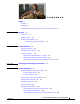
CONTENTS Preface v Overview v Organization v Obtaining Documentation, Obtaining Support, and Security Guidelines CHAPTER 1 Overview 1-1 Introduction 1-1 Package Contents 1-2 IP Camera Physical Details 1-3 General Purpose I/O Terminal Block CHAPTER 2 v Camera Installation 1-5 2-1 Installation Guidelines 2-1 Warnings Before Installation 2-1 IP Camera Installation 2-4 Mounting the IP Camera Directly to a Surface 2-4 Mounting the IP Camera Flush with a Surface 2-7 Mounting the IP camer
Contents Deleting Encrypted Video Files from the SD Memory Card Decrypting Encrypted Video Files 4-15 4-14 INDEX Cisco Video Surveillance 6020 IP Camera Installation Guide iv OL-28120-02
Preface Overview This document, Cisco Video Surveillance 6020 IP Camera Installation Guide, provides information about installing and deploying the Cisco Video Surveillance 6020 IP Camera. Organization This manual is organized as follows: Chapter 1, “Overview” Provides an overview of the IP camera and its features. Chapter 2, “Camera Installation” Provides instructions for physically installing the IP camera.
Preface Cisco Video Surveillance 6020 IP Camera Installation Guide vi OL-28120-02
CH A P T E R 1 Overview This chapter describes the Cisco Video Surveillance 6020 IP Camera, and includes the following topics: • Introduction, page 1-1 • Package Contents, page 1-2 • IP Camera Physical Details, page 1-3 Introduction The Cisco Video Surveillance 6020 IP camera is an indoor, high definition, professional fixed dome IP camera with industry-leading image quality and processing power.
Chapter 1 Overview Package Contents Package Contents The Cisco Video Surveillance 6020 IP Camera package includes the following items: • Cisco Video Surveillance 6020 IP Camera (1) • Installation template and alignment sticker (1) • Wall anchors (3) • Screws (3) • Black cover (1) • Ethernet cable (1) • RJ45 coupler (1) • Extra set of labels (3) • Cisco documentation pointer card (1) • Cisco RoHS document (1) Cisco Video Surveillance 6020 IP Camera Installation Guide 1-2 OL-28120-02
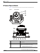
Chapter 1 Overview IP Camera Physical Details IP Camera Physical Details Figure 1-1 and the table that follows describe the physical features of the 6020 IP camera. Figure 1-1 IP Camera Details 1 2 3 4 5 6 7 8 10 9 11 1 Light sensor Senses the level of ambient light to determine when to switch day/night mode. 2 Varifocal lens IP camera lens that changes focus as the focal length changes.
Chapter 1 Overview IP Camera Physical Details 4 Tilt adjustment screw Used when tilting the camera to set the field of view. 5 Recessed Reset button Recessed button that reboots the IP camera or resets it to a default state. You can use a pin or paper clip to depress it. It can be used any time that the IP camera is on and can have various effects, as described in the “Resetting the IP Camera” section on page 4-4.
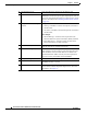
Chapter 1 Overview IP Camera Physical Details General Purpose I/O Terminal Block Figure 1-2 shows the pin locations and descriptions. Figure 1-2 GPIO Terminal Block Pin Locations and Descriptions 1 2 3 4 5 6 7 8 Note Pin Description 1 DC 12V- 2 DC 12V+ 3 AC 24V_2 4 AC 24V_1 5 DI- (GND) 6 DI+ 7 DO- 8 DO+ (+12V) The maximum output load from pins 7 and 8 is 400mA.
Chapter 1 Overview IP Camera Physical Details Cisco Video Surveillance 6020 IP Camera Installation Guide 1-6 OL-28120-02
CH A P T E R 2 Camera Installation This chapter provides information and instructions for installing the Cisco Video Surveillance 6020 IP Camera, and includes the following topics: • Installation Guidelines, page 2-1 • Warnings Before Installation, page 2-1 • IP Camera Installation, page 2-4 Installation Guidelines This section describes how to install the IP camera.
Chapter 2 Camera Installation Warnings Before Installation • Do not place the IP Camera around heat sources, such as a television or oven. • Refer to your user’s manual for the operating temperature. • Keep the IP Camera away from direct sunlight. • Do not place the IP Camera in high humidity environments. • Do not place the IP Camera on unsteady surfaces. • Do not touch the IP Camera during a lightning storm.
Chapter 2 Camera Installation Warnings Before Installation • Do not disassemble the IP Camera. • Do not insert sharp or tiny objects into the IP Camera. • Do not drop the IP Camera. Warning Installation of the equipment must comply with local and national electrical codes. Statement 1074 Warning The power supply must be placed indoors. Statement 331 Note If you use the IP camera outdoors, place the camera and the power supply in a suitable NEMA enclosure.
Chapter 2 Camera Installation IP Camera Installation IP Camera Installation Install the 6020 IP camera using one of the following procedures: • Mounting the IP Camera Directly to a Surface, page 2-4 • Mounting the IP Camera Flush with a Surface, page 2-7 • Mounting the IP camera with a Vandal Resistant Enclosure, page 2-10 Mounting the IP Camera Directly to a Surface To directly mount the 6020 IP camera to a surface, complete the following steps: Procedure Step 1 Attach the included alignment stic
Chapter 2 Camera Installation IP Camera Installation The GPIO terminal block pin locations and descriptions are as follows: Pin 1 2 3 4 5 6 7 8 Step 6 Note 1 2 3 4 5 6 7 8 Description 12 VDC12 VDC+ 24 VAC 24 VAC DIDI+ DODO+ (Optional) Use a mini cable with BNC connector to temporarily attach an NTSC or PAL compliant analog video display device to the analog video out port on the IP camera.
Chapter 2 Camera Installation IP Camera Installation Step 9 Install the black cover. Step 10 Attach the dome cover to the IP camera base by aligning it with the mounting holes. Step 11 Use the included screwdriver to tighten the four dome cover screws to secure the dome cover to the IP camera. Make sure all parts of the IP camera are securely installed.
Chapter 2 Camera Installation IP Camera Installation Mounting the IP Camera Flush with a Surface To mount the 6020 IP camera flush with a surface, complete the following steps: Procedure Step 1 Secure the IP camera inside the camera housing using the two included screws. Step 2 Remove the ceiling tile from the location at which you want to mount the IP dome and cut a 7-3/4 inch (19.68 cm) diameter hole in the center of the tile.
Chapter 2 Camera Installation IP Camera Installation Step 6 Connect a shielded twisted pair (STP) Category 5 or higher network cable to the LAN port on the back of the camera through the cutout in the camera housing. Connect the other end of the network cable to a 10/100/BaseT router or switch. If your network provides PoE, the IP camera powers on.
Chapter 2 Camera Installation IP Camera Installation Step 11 While viewing video from the IP camera, perform the following steps to adjust the 3-axis field of view: a. Grip the two tilt adjustment screws and pan the IP camera left or right. b. Loosen the two thumb screws, tilt the IP camera, then tighten the thumb screws. c. Rotate the IP camera to adjust the image horizontal orientation. Step 12 Install the black cover.
Chapter 2 Camera Installation IP Camera Installation What to do next Complete the following procedures: • After you install the IP camera, follow the instructions in the “Performing the Initial Setup of the IP Camera” section on page 3-1 to access the IP camera through your network. • After completing the initial setup, use the IP camera user interface to adjust the focal length and zoom factor. For more information, see the “Adjusting the IP Camera Focus and Zoom” section on page 4-3.
Chapter 2 Camera Installation IP Camera Installation Step 5 Secure the IP camera to the conduit base with two included screws. Step 6 Feed a shielded twisted pair (STP) Category 5 or higher network cable through the conduit base and connect to the LAN port on the back of the camera. Connect the other end of the network cable to a 10/100/BaseT router or switch. If your network provides PoE, the IP camera powers on.
Chapter 2 Camera Installation IP Camera Installation Note The mini cable with BNC adapter is included in the audio/video cables accessory kit, which you can purchase from Cisco (Cisco part number CIVS-AVCABLE). Analog video is enabled by default to allow you to adjust the camera field of view during installation.
Chapter 2 Camera Installation IP Camera Installation Step 13 Use the included wrench and tighten the four dome cover screws to secure the dome cover to the camera. Make sure all parts of the camera are securely installed. What to do next Complete the following procedures: • After you install the IP camera, follow the instructions in the “Performing the Initial Setup of the IP Camera” section on page 3-1 to access the IP camera through your network.
Chapter 2 Camera Installation IP Camera Installation Cisco Video Surveillance 6020 IP Camera Installation Guide 2-14 OL-28120-02
CH A P T E R 3 Performing the Initial Setup of the IP Camera After you install IP camera as described in the Chapter 2, “Camera Installation,” or after you perform a factory reset procedure, you must access the IP camera and make initial configuration settings. These settings include administrator and root passwords, and whether the IP camera can be accessed through an HTTP connection in addition to the default HTTPS (HTTP secure) connection.
Chapter 3 Step 3 Performing the Initial Setup of the IP Camera In the Password and Confirm Password fields of the admin row, enter a password for the IP camera administrator. You must enter the same password in both fields. The password is case sensitive and must contain at least eight characters, which can be letters, numbers, and special characters, but no spaces. Special characters are: ! " # $ % & ' ( ) * + , - . : ; < = > ? @ [ \ ] ^ _ ` { | } ~.
CH A P T E R 4 Camera Management This chapter provides information and instructions for managing the Cisco Video Surveillance 6020 IP Camera, and includes the following topics: • Understanding the IP Camera User Interface, page 4-1 • Adjusting the IP Camera Focus and Zoom, page 4-3 • Powering the IP Camera On or Off, page 4-4 • Resetting the IP Camera, page 4-4 • Viewing Live Video, page 4-4 • Managing the Local Storage, page 4-12 Understanding the IP Camera User Interface After you log in to
Chapter 4 Camera Management Understanding the IP Camera User Interface Table 4-1 Links in the IP Camera Windows (continued) Link Description Privilege Level View Video Displays the Camera Video & Control window. Administrator You may be prompted to install ActiveX controls when trying to User access this window for the first time. ActiveX controls are required to view video from the IP camera. Follow the on-screen prompts to install ActiveX controls.
Chapter 4 Camera Management Adjusting the IP Camera Focus and Zoom Table 4-2 Home Window Information (continued) Field Description Gateway Address IP address of the gateway through which the IP camera is connected. Primary DNS IP address of the primary DNS server, if configured for the IP camera. Secondary DNS IP address of the secondary DNS server, if configured for the IP camera. IO Port Status Input Port 1 Current state of input port 1 on the IP camera.
Chapter 4 Camera Management Powering the IP Camera On or Off Powering the IP Camera On or Off The IP camera does not include an on/off switch. You power it on or off by connecting it to or disconnecting it from a power source. When you power off the IP camera, configuration settings are retained. To power on the IP camera, take either of these actions: • Use an STP (shielded twisted pair) Category 5 or higher network cable to connect the IP camera to a network switch that provides 802.3af compliant PoE.
Chapter 4 Camera Management Viewing Live Video To view live video, log in to the IP camera, then click View Video in the IP camera Main window menu bar. The Camera Video & Control window appears. This window displays live video from the camera and lets you control a variety of camera and display functions. The controls that you see in the Camera Video & Control window depend on your IP camera privilege level and the configurations settings for the IP camera.
Chapter 4 Camera Management Viewing Live Video Table 4-4 Camera Video & Control Window Controls (continued) Control Description Flip button Rotates the video image by 180 degrees. Mirror button Reverses the video image. Restore button Displays the default video image, which is not rotated and not reversed. Full Screen button Displays the video image in full screen mode. To return to normal display mode, click the full screen image.
Chapter 4 Camera Management Viewing Live Video Table 4-4 Camera Video & Control Window Controls (continued) Control Description Speaker Volume slider When the speaker is unmuted, drag this slider to adjust the volume at which and field your PC speakers play the audio from the IP camera, or enter a value from 0 through 100 and press the Enter key. The default value is 50.
Chapter 4 Camera Management Viewing Live Video Table 4-4 Camera Video & Control Window Controls (continued) Control Description Sharpness slider To control the sharpness of the video from the IP camera, drag the slider, or enter a value from 1 through 100 and press the Enter key. A higher value increases the sharpness and a lower value decreases the sharpness. The default value is 50.
Chapter 4 Camera Management Viewing Live Video Table 4-4 Camera Video & Control Window Controls (continued) Control Description Iris Mode The Iris mode is available only when the Exposure mode is set to Auto. Choose one of the following Iris modes: • Indoor—Suitable for Indoor conditions. • Outdoor—Suitable for Outdoor conditions. Default mode is Indoor.
Chapter 4 Camera Management Viewing Live Video Table 4-4 Camera Video & Control Window Controls (continued) Control Description Up Arrow toggle button Click the Up Arrow to display the motion detection controls. The button changes to the Down Arrow button. Down Arrow toggle button Click the Down Arrow button to hide the motion detection controls. The button changes to the Up Arrow button.
Chapter 4 Camera Management Viewing Live Video Table 4-4 Camera Video & Control Window Controls (continued) Control Description Full Screen check box Becomes available when you click check Enable Motion Detection check box. Check the Full Screen check box to cause the IP camera to examine the entire video field for activity.
Chapter 4 Camera Management Managing the Local Storage Table 4-4 Camera Video & Control Window Controls (continued) Control Description Privacy Zone Up Arrow toggle button Down Arrow toggle button Click the Up Arrow to display the privacy zone controls. The button changes to the Down Arrow button. Click the Down Arrow button to hide the privacy zone controls. The button changes to the Up Arrow button.
Chapter 4 Camera Management Managing the Local Storage This section includes the following local storage management topics: • Downloading and Installing the Cisco SD Utility, page 4-13 • Formatting the SD Memory Card, page 4-13 • Downloading Encrypted Video Files from the SD Memory Card, page 4-14 • Deleting Encrypted Video Files from the SD Memory Card, page 4-14 • Decrypting Encrypted Video Files, page 4-15 Downloading and Installing the Cisco SD Utility Procedure Step 1 Perform the following
Chapter 4 Camera Management Managing the Local Storage The SD memory card is formatted using a FAT32 partition. If the SD memory card was previously formatted using a different partition type, such as NTFS, you are prompted to verify that you want to format the SD memory card using the FAT32 partition. Downloading Encrypted Video Files from the SD Memory Card Procedure Step 1 Double-click the Cisco SD Utility icon to open the utility.
Chapter 4 Camera Management Managing the Local Storage The selected files are deleted from the SD memory card. Decrypting Encrypted Video Files Before you begin • Download the encrypted video files to your PC, or move the SD memory card containing the encrypted video files from the IP camera to your PC. For more information about downloading the encrypted video files, see the “Downloading Encrypted Video Files from the SD Memory Card” section on page 4-14.
Chapter 4 Camera Management Managing the Local Storage Cisco Video Surveillance 6020 IP Camera Installation Guide 4-16 OL-28120-02
INDEX A D About link decrypting video files 4-2 ActiveX controls 4-2 audio controls in Camera Video & Control window B 4-6 4-15 deleting files from SD memory card 4-14 DHCP, obtaining IP address through 3-1 downloading video files from SD memory card 4-14 F brightness factory reset 4-7 4-4 focus/zoom accessing controls C controls 4-11 4-11 formatting SD memory card camera 4-13 See IP camera camera settings H picture adjustments brightness contrast help, for IP camera window
Index IP camera enabling accessing through a web browser connecting to for the first time installation mounting to ceiling or wall 2-10 PC microphone PC speaker 4-5 4-4 powering on 4-4 2-10 4-6 4-6 P 4-5 windows 4-10, 4-12 muting 4-2 powering off tilting 4-10, 4-11 Motion detection controls 2-1 logging out of 4-10, 4-11 threshold 3-1 mounting to ceiling or wall panning sensitivity 3-1 2-1 warnings 4-10 4-2 panning 4-5 password requirements for L 3-2 picture adjustment
Index SD memory card W deleting video files from 4-14 downloading video files from formatting warnings before installation 4-14 white balance mode 4-13 sensitivity, for motion detection sharpness Z 4-2 displaying zoom 4-2 accessing controls 4-8 speaker zoom controls volume 4-8 4-10, 4-11 Setup window description 2-1 4-11 4-11 4-7 storage Cisco SD utility, downloading decrypting video files managing 4-13 4-15 4-12 SD memory card deleting video files from 4-14 downloading vi
Index Cisco Video Surveillance 6020 IP Camera Installation Guide IN-4 OL-28120-02