C H A P T E R 7 PIX 535 This chapter describes the installation of the PIX 535, and includes the following sections: • PIX 535 Product Overview, page 7-1 • Installing the PIX 535, page 7-5 • PIX 535 Feature Licenses, page 7-6 • Installing Failover, page 7-8 • Installing LAN-Based Failover, page 7-9 • Replacing a Lithium Battery, page 7-10 • Installing a Memory Upgrade, page 7-11 • Installing a Circuit Board in the PIX 535, page 7-14 • Installing the PIX 535 DC Model, page 7-21 PIX 535 Pr
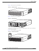
Chapter 7 PIX 535 PIX 535 Product Overview Figure 7-1 shows the front view of the PIX 535. PIX 535 Front Panel CISCO SECURITY PIX 535 SERIES F I R E W A L L POWER 61915 Figure 7-1 ACTIVE Figure 7-2 shows the rear view of the PIX 535. PIX 535 Rear Panel STATUS 61916 Figure 7-2 STATUS The PIX 535 has a fixed RJ-45 Console connector and a DB-15 Failover cable connector the USB port is not used at the present time. Figure 7-3 shows the PIX 535 front panel LEDs.
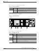
Chapter 7 PIX 535 PIX 535 Product Overview Table 7-1 lists the states of the PIX 535 front panel LEDs. Table 7-1 PIX 535 Front Panel LEDs LEDs State Description POWER On Unit has power. ACT On On when the unit is the active failover unit. If failover is present the light is on when the unit is the active unit. Off Off when the unit is in standby mode. Figure 7-4 shows the PIX 535 rear panel LEDs.
Chapter 7 PIX 535 PIX 535 Product Overview PIX 535 Network Interface Description There are three separate buses for the nine interface slots in the PIX 535. The interfaces are counted from right to left on the PIX 535.
Chapter 7 PIX 535 Installing the PIX 535 Table 7-3 lists the relative throughput of the Gigabit Ethernet combinations.
Chapter 7 PIX 535 PIX 535 Feature Licenses PIX 535 Network Interface Installation Note If your PIX security appliance model supports a failover configuration, complete the steps that follow only on the active (primary) unit. To connect interfaces to the PIX 535, perform the following steps: Step 1 Connect the cable so that you have either a DB-9 or DB-25 connector on one end as required by the serial port for your computer, and the other end is the RJ-45 connector.
Chapter 7 PIX 535 PIX 535 Feature Licenses For information on upgrading feature licenses or downloading the latest software versions, refer to the configuration guide online at: http://www.cisco.com/en/US/products/sw/secursw/ps2120/prod_configuration_guides_list.html.
Chapter 7 PIX 535 Installing Failover Installing Failover To set up a failover connection, perform the following steps: Step 1 Power off both the primary and secondary units. Note Step 2 Both chassis must be the same model number, have at least as much RAM, have the same Flash memory size, and be running the same software version. Note that the PIX-4FE and PIX-4FE-66 cards are considered equivalent and interchangeable.
Chapter 7 PIX 535 Installing LAN-Based Failover Caution Step 7 Do not turn the power on until the units are connected and the primary unit is configured completely. Power the primary unit on first, then power on the secondary unit. Within a few seconds, the active unit automatically downloads its configuration to the standby unit. If the primary unit fails, the secondary unit automatically becomes active. Note All enabled interfaces must be connected between the active and standby units.
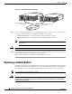
Chapter 7 PIX 535 Replacing a Lithium Battery Figure 7-6 LAN-Based Failover Connections PIX 535 PIX 535 STATUS Dedicated Ethernet interface 87368 STATUS 87366 STATUS STATUS Dedicated Ethernet interface Hub/switch Step 5 If you are using Stateful Failover, use one of the following types of connections, that is appropriate for your system, between the dedicated interfaces on the PIX security appliance: • 100BaseTX full duplex on a dedicated switch or dedicated VLAN of a switch • 1000BaseTX
Chapter 7 PIX 535 Installing a Memory Upgrade Installing a Memory Upgrade The following statement applies to DC models only: Warning Before performing any of the following procedures, ensure that power is removed from the DC circuit. To ensure that all power is OFF, locate the circuit breaker on the panel board that services the DC circuit, switch the circuit breaker to the OFF position, and tape the switch handle of the circuit breaker in the OFF position.
Chapter 7 PIX 535 Installing a Memory Upgrade Step 7 Locate the system memory sockets (see Figure 7-7). Populate memory Bank 0 first, then Bank 1. Memory sockets J40 and J43 comprise Bank 0; J41 and J44 comprise Bank 1. The PIX security appliance comes with 512 MB of RAM installed by default, so Bank 0 (J40 and J43) should be populated already. Install the additional 512 MB of RAM in Bank 1 (J41 and J44). The memory DIMM pair that comprises a memory bank must be identical.
Chapter 7 PIX 535 Installing a Memory Upgrade Step 8 Install the first DIMM strip in socket J41 and the second DIMM strip in socket J44, as shown in Figure 7-8 and Figure 7-9. a. Carefully grasp the DIMM strip from either end, being careful not to touch the components on the strip. Note that the DIMM strip is notched, which prevents it from being installed incorrectly. So, do not force installation. b.
Chapter 7 PIX 535 Installing a Circuit Board in the PIX 535 Step 12 Reconnect all cables to the security appliance and plug it into its power source. Step 13 Power on the security appliance. Note You can verify that the security appliance recognizes the new RAM memory that you installed by looking at the system startup messages or by entering the show version command. Installing a Circuit Board in the PIX 535 The 4-port 64 bit/66 MHz FE card (PIX-4FE-66) is supported in software Versions 6.3, 6.
Chapter 7 PIX 535 Installing a Circuit Board in the PIX 535 Table 7-4 PIX 535 Interface Options Restricted Interface Options Unrestricted Interface Options 8 GE 9 GE 8 GE + 1 VPN Accelerator 8 GE + 1 FE 7 GE + 1 FE 8 GE + 1 VPN Accelerator 7 GE + 1 FE + 1 VPN Accelerator 7 GE + 2 FE 6 GE + 2 FE 7 GE + 1 FE + 1 VPN Accelerator 6 GE + 2 FE + 1 VPN Accelerator 6 GE + 3 FE 5 GE + 3 FE 6 GE + 2 FE + 1 VPN Accelerator 5 GE + 3 FE + 1 VPN Accelerator 5 GE + 4 FE 4 GE + 4 FE 5 GE + 3 FE + 1 V
Chapter 7 PIX 535 Installing a Circuit Board in the PIX 535 Circuit Board Slot Description There are nine circuit board slots (see Figure 7-10) using three separate buses for the PIX 535.
Chapter 7 PIX 535 Installing a Circuit Board in the PIX 535 Installing a Circuit Board Note It is not necessary to remove the chassis cover on the PIX 535 to install or replace a circuit board. A component tray, that slides out from the rear panel, contains slots for installing circuit boards and memory boards. To install a circuit board in the PIX 535, perform the following steps: Step 1 Locate the grounding strap from the accessory kit.
Chapter 7 PIX 535 Installing a Circuit Board in the PIX 535 Figure 7-12 4-Port Circuit Board Overlap 27884 Overlap Note If you are installing a 4-port circuit board, note that the circuit board will overlap the slot connector on the motherboard. This does not affect the use or operation of the circuit board. Figure 7-12 illustrates how this appears.
Chapter 7 PIX 535 Installing a Circuit Board in the PIX 535 An illustration of the 16 MB Flash circuit board is shown in Figure 7-13. 33011 Figure 7-13 16 MB Flash Circuit Board You must observe the following when installing a 16 MB Flash circuit board: • The PIX security appliance must have a minimum of 32 MB of RAM memory. • You must obtain a new activation key if you use 3DES. • The PIX security appliance should not be downgraded to a software revision lower than 5.
Chapter 7 PIX 535 Installing a Circuit Board in the PIX 535 Step 5 Remove any previously installed Flash memory circuit boards from the unit. Step 6 The jumper on the PIX security appliance 16 MB Flash circuit board must not be removed or repositioned. The PIX security appliance system will not work if this jumper is moved. Step 7 Install the 16 MB Flash circuit board into an available ISA slot in the PIX security appliance chassis.
Chapter 7 PIX 535 Installing the PIX 535 DC Model Note You must use a GE failover link when connecting the PIX 535 with GE interfaces. The Gigabit Ethernet circuit board and the fiber optic cable connection are shown in Figure 7-15.
Chapter 7 PIX 535 Installing the PIX 535 DC Model Step 3 Terminate the DC input wiring on a DC source capable of supplying at least 15 amps. A 15-amp circuit breaker is required at the -48 VDC facility power source. An easily accessible disconnect device should be incorporated into the facility wiring. Step 4 Be sure the PIX 535 power is off by checking the power switch at the rear of the unit.
Chapter 7 PIX 535 Installing the PIX 535 DC Model Step 9 Reconnect power to the PIX 535. After wiring the DC power supply, remove the tape from the circuit breaker switch handle and reinstate power by moving the handle of the circuit breaker to the ON position. Step 10 If needed, install the interface boards as described in the “Installing a Circuit Board in the PIX 535” section on page 7-14. Step 11 Power on the unit from the switch at the rear of the unit.
Chapter 7 PIX 535 Installing the PIX 535 DC Model Cisco PIX Security Appliance Hardware Installation Guide 7-24 78-15170-03