Cisco Video Surveillance 4300 and 4500 High-Definition IP Cameras User Guide Americas Headquarters Cisco Systems, Inc. 170 West Tasman Drive San Jose, CA 95134-1706 USA http://www.cisco.
NOTICE. ALL STATEMENTS, INFORMATION, AND RECOMMENDATIONS IN THIS MANUAL ARE BELIEVED TO BE ACCURATE BUT ARE PRESENTED WITHOUT WARRANTY OF ANY KIND, EXPRESS OR IMPLIED. USERS MUST TAKE FULL RESPONSIBILITY FOR THEIR APPLICATION OF ANY PRODUCTS. THE SOFTWARE LICENSE AND LIMITED WARRANTY FOR THE ACCOMPANYING PRODUCT ARE SET FORTH IN THE INFORMATION PACKET THAT SHIPPED WITH THE PRODUCT AND ARE INCORPORATED HEREIN BY THIS REFERENCE.
CONTENTS Preface v Overview v Organization v Obtaining Documentation, Obtaining Support, and Security Guidelines CHAPTER 1 Overview 1-1 IP Camera Features 1-1 IP Camera Physical Details 1-2 DC Auto Iris Lens Connector Pinouts Package Contents CHAPTER 2 Getting Started 1-6 1-6 2-1 Installing the IP Camera 2-1 Performing the Initial Setup of the IP Camera Accessing the IP Camera Adjusting Back Focus on the IP Camera Powering the IP Camera On or Off Resetting the IP Camera 3 2-5 2-6
Contents Network Setup Windows 3-16 Basic Settings Window 3-16 IP Addressing Window 3-17 Time Settings Window 3-18 Discovery Settings Window 3-20 SNMP Settings Window 3-21 802.
Preface Overview This document, Cisco Video Surveillance IP Camera User Guide, provides information about installing, configuring, using, managing, and troubleshooting the Cisco 4000 Series Video Surveillance High-Definition IP Cameras.
Preface Subscribe to the What’s New in Cisco Product Documentation as a Really Simple Syndication (RSS) feed and set content to be delivered directly to your desktop using a reader application. The RSS feeds are a free service and Cisco currently supports RSS version 2.0.
CH A P T E R 1 Overview This chapter provides an overview of the Cisco 4000 Series Video Surveillance High-Definition IP Cameras and their features.
Chapter 1 Overview IP Camera Physical Details • Two-way audio communication—Audio can be encoded with the video. With the internal or optional external microphone and optional external speaker, you can communicate with people at the IP camera location while you are in a remote location and viewing images from the IP camera. • Multi-protocol support—Supports these protocols: DHCP, FTP, HTTP, HTTPS, NTP, RTP, RTSP, SMTP, SNMP v2 and v3, SSL/TLS, and TCP/IP.
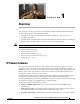
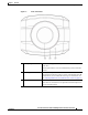
Chapter 1 Overview IP Camera Physical Details Figure 1-1 1 Front of IP Camera Lens opening The IP camera supports a variety of C and CS mount lenses, which attach here. For best performance, Cisco recommends that you use a DC auto iris lens. 2 Focus ring Allows you to adjust the back focus of the IP camera. You must loosen the focus ring hex screw on the bottom of the IP camera before you can rotate the focus ring.
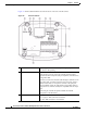
Chapter 1 Overview IP Camera Physical Details Figure 1-2 and the table that follows describe the items on the rear of the IP camera. Figure 1-2 Rear of IP Camera 1 Power LED Lights bright when the IP camera is powering up. Lights dim when the camera is IP operating 2 Audio Port Allows the connection of the audio Y cable that is provided with the IP camera. You can connect an optional external speaker, optional external microphone (with pre-amplifier), or both devices through this cable.
Chapter 1 Overview IP Camera Physical Details 4 LAN port Accepts a standard LAN cable to connect the IP camera to a 100BaseT hub, router, or switch. 5 Network Activity LED Indicates information about the network connections as follows: 6 Power input • Lit amber—LAN connection is detected • Off—LAN connection is not detected • Blinking—Data is being transmitted or received via the LAN connection Provides for the connection of an optional 12 V, 1 amp DC power adapter or 24 VAC power adapter.
Chapter 1 Overview DC Auto Iris Lens Connector Pinouts DC Auto Iris Lens Connector Pinouts Figure 1-4 and the table that follows describe the pinouts of the DC auto iris lens connector on the IP camera. Figure 1-4 DC Auto Iris Lens Connector Pinouts Pin Function 1 Damp – 2 Damp + 3 Drive + 4 Drive – Package Contents The the Cisco Video Surveillance IP Camera package includes these items: • Camera • Lens opening dust cap • USB port cover • Audio Y cable, 3.5 mm male mono jack / dual 3.
CH A P T E R 2 Getting Started This chapter provides instructions for installing and performing the initial setup of the Cisco Video Surveillance IP Camera. It also describes how to access the IP camera through a web browser so that you can configure it or view video from it, and how to perform other important tasks.
Chapter 2 Getting Started Installing the IP Camera Warning The power supply must be placed indoors. Statement 331 Note If you use the IP camera outdoors, place the camera and the power supply in a suitable NEMA enclosure. Warning This product must be connected to a power-over-ethernet (PoE) IEEE 802.3af compliant power source or an IEC60950 compliant limited power source. Statement 353 Caution Inline power circuits provide current through the communication cable.
Chapter 2 Getting Started Installing the IP Camera Table 2-1 Installing the IP Camera (continued) Action Step 3 Explanation Optional. Use the audio Y cable that is provided with The audio cable that is provided with the IP includes two the IP camera to connect a speaker, microphone, or both plugs. The cable from an external speaker connects to the devices to the audio port on the rear of the IP camera. Audio Out plug on the audio cable.
Chapter 2 Getting Started Installing the IP Camera Table 2-1 Installing the IP Camera (continued) Action Step 7 Explanation If you are using the IP camera on a network connection First, connect the bare wires at the end of the power that does not provide PoE, connect the optional 12 VDC adapter to the terminal block that is provided with the IP or 24 VAC power adapter.
Chapter 2 Getting Started Performing the Initial Setup of the IP Camera Performing the Initial Setup of the IP Camera After you install IP camera as described in the “Installing the IP Camera” section on page 2-1, or after you perform a factory reset procedure, you must access the IP camera and make initial configuration settings.
Chapter 2 Getting Started Accessing the IP Camera Step 6 After the IP camera reboots, start Internet Explorer and, in the Address field, enter the following: protocol://ip_address where: Step 7 • protocol is HTTPS or HTTP. (You can use HTTP only if you enabled it in Step 4.) • ip_address is the IP address that you used in Step 1. If you are prompted to install ActiveX controls, which are required to view video from the IP camera, follow the on-screen prompts to do so.
Chapter 2 Getting Started Understanding the IP Camera User Interface • ip_address is the IP address of the IP camera. The default IP address is 192.168.0.100. • port_number is the port number that is used for HTTPS or HTTP connections to the IP camera. You do not need to enter a port number if you are connecting through the default HTTPS port 443 or the default HTTP port 80. For example, • Enter the following for a secure connection if the IP address is 192.168.0.
Chapter 2 Getting Started Understanding the IP Camera User Interface Table 2-2 Links in the IP Camera Windows Link Description Privilege Level Refresh Updates the information in the window that is currently displayed. Administrator User Home Displays the Home window. Administrator View Video Displays the Camera Video/Control window. Administrator User You may be prompted to install ActiveX controls when trying to access this window for the first time.
Chapter 2 Getting Started Adjusting Back Focus on the IP Camera Table 2-3 Home Window Information (continued) Field Description Configuration Type Method by which the IP camera obtains its IP address. To configure this method, see the “IP Addressing Window” section on page 3-17. LAN IP IP address of the LAN to which the IP camera is connected. To configure this IP address, see the “IP Addressing Window” section on page 3-17. Subnet Mask Subnet mask of the LAN to which the IP camera is connected.
Chapter 2 Getting Started Powering the IP Camera On or Off To adjust the back focus, perform the following steps while viewing video from the camera. For information about viewing video, see Chapter 4, “Viewing Live Video.” Procedure Step 1 With a lens attached to the IP camera, use the 0.9mm Allen wrench that is supplied with the IP camera to loosen the focus ring hex screw. This screw is on the bottom of the camera just behind the focus ring.
Chapter 2 Getting Started Resetting the IP Camera Table 2-4 Resetting the IP Camera Reset Type Procedure Remarks Reboot. Press and immediately release the Reset button. This action is equivalent to powering the IP camera down and then powering it up. Settings that are configured for the IP camera are retained. Factory reset. Press and hold the button for at least 15 seconds. Sets all IP camera options to their default values.
Chapter 2 Getting Started Resetting the IP Camera Cisco Video Surveillance 4300 and 4500 High-Definition IP Cameras User Guide 2-12 OL-19609-04
CH A P T E R 3 Configuring and Managing the IP Camera The Cisco Video Surveillance IP Camera provides configuration windows that you use to configure and manage the IP camera. This chapter explains how to access the configuration windows, describes each window, and provides detailed information about the options that are available in each window.
Chapter 3 Configuring and Managing the IP Camera Feature Setup Windows The configuration windows are organized as follows: • Feature Setup – Streaming – Camera – Video Overlay – IO Ports – Pan/Tilt – Event – Patrol Sequence – Analytics • Network Setup – Basic – IP Addressing – Time – Discovery – SNMP – 802.
Chapter 3 Configuring and Managing the IP Camera Feature Setup Windows • Pan Tilt Settings Window, page 3-9 • Event Notification Window, page 3-10 • Patrol Sequence Window, page 3-14 • Analytics Windows, page 3-16 Streaming Settings Window The Streaming Settings window provides options for configuring audio and video streams from the IP camera. You can configure settings for the primary and an optional secondary video stream.
Chapter 3 Configuring and Managing the IP Camera Feature Setup Windows If you change any options in this window, you must click the Save Settings button to save the changes. If you do not click this button, changes are not retained when you exit the window. Save Settings appears at the bottom of the window. You may need to scroll down to it. Table 3-2 describes the options in the Streaming Settings window.
Chapter 3 Configuring and Managing the IP Camera Feature Setup Windows Table 3-2 Streaming Settings Window Options (continued) Option Description Multicast Video Port Enter the port on which the IP camera sends a multicast video stream. Valid values are even numbers 1024 through 65532. Multicast Audio Port Enter the port on which the IP camera sends a multicast audio stream. Valid values are even numbers 1024 through 65532.
Chapter 3 Configuring and Managing the IP Camera Feature Setup Windows Table 3-2 Streaming Settings Window Options (continued) Option Description Audio Sampling Rate Display only. Displays the sampling rate for audio from the IP camera. Audio Resolution Display only. Displays the resolution for audio from the IP camera.
Chapter 3 Configuring and Managing the IP Camera Feature Setup Windows Table 3-3 Camera Settings Window Options (continued) Option Description Sensitivity Designates how the iris opening in the IP camera lens adjusts when auto iris mode is enabled. As sensitivity increases, the auto iris closes more to reduce the light level and increase the depth of field in bright environments. However, a high sensitivity may cause the image to oscillate between bright and dim.
Chapter 3 Configuring and Managing the IP Camera Feature Setup Windows Table 3-3 Camera Settings Window Options (continued) Option Description End Time Enter the time, in 24 hour format, that the camera disables its night filter. Video Overlay Settings Window The Video Overlay Settings window provides options for configuring overlay information that appears on the video image in the Camera Video/Control window.
Chapter 3 Configuring and Managing the IP Camera Feature Setup Windows If you change the option in this window, you must click the Save Settings button to save the change. If you do not click this button, changes are not retained when you exit the window. Save Settings appears at the bottom of the window. You may need to scroll down to it. Table 3-5 describes the option in the IO Ports Settings window. Table 3-5 IO Ports Settings Window Options Option Description Input Ports Area Port # Display only.
Chapter 3 Configuring and Managing the IP Camera Feature Setup Windows Table 3-6 Pan Tilt Settings Window Options Option Description Pan/Tilt Area Pan and Tilt Enabled Check this check box to enable pan and tilt operation for the IP camera. Protocol Display only. Indicates the protocol for the pan/tilt functionality. Address Enter the logical address of the external PTZ device. To determine this address, refer to the documentation for that device.
Chapter 3 Configuring and Managing the IP Camera Feature Setup Windows – Event state—Indicates whether the event is active or inactive at the time that the event was detected for this notification – Event description—Description of the event.
Chapter 3 Configuring and Managing the IP Camera Feature Setup Windows Table 3-7 Event Notification Window Options (continued) Option Description Actions Check the desired check boxes to designate that actions that the IP camera takes when the corresponding trigger occurs. • Email—Sends information about the event in an e-mail message to the designated recipient. You design the recipient and configure other e-mail options in other fields in this window.
Chapter 3 Configuring and Managing the IP Camera Feature Setup Windows Table 3-7 Event Notification Window Options (continued) Option Description User Name If authentication is required on the primary server to which HTTP messages are sent, enter the user name. Password If authentication is required on the primary server to which HTTP messages are sent, enter the password.
Chapter 3 Configuring and Managing the IP Camera Feature Setup Windows Table 3-7 Event Notification Window Options (continued) Option Description Secondary SMTP Server Identify an optional secondary SMTP server that is used for sending e-mail by choosing IP Address or Hostname from the drop-down list and entering the IP address or host name in the corresponding field. Secondary SMTP Port Enter the port number for the secondary SMTP server.
Chapter 3 Configuring and Managing the IP Camera Feature Setup Windows To display the Patrol Sequence window, access the configuration windows as described in the “Performing the Initial Setup of the IP Camera” section on page 2-5, click Feature Setup, then click Patrol Sequence. If you change any options in this window, you must click the Save Settings button to save the change. If you do not click this button, changes are not retained when you exit the window.
Chapter 3 Configuring and Managing the IP Camera Network Setup Windows Analytics Windows The Analytics windows provide access to options for configuring the Cisco video analytics feature. To display the Analytics windows, access the configuration windows as described in the “Performing the Initial Setup of the IP Camera” section on page 2-5, click Feature Setup, then click Analytics. A new browser session starts and the Analytics Home window appears.
Chapter 3 Configuring and Managing the IP Camera Network Setup Windows Table 3-9 Basic Settings Window Options Option Description Basic Settings Area ID Enter a unique identification for the IP camera, which is used to identify the IP camera to various external applications. The ID can contain up to 64 numbers. Name Enter a name for the IP camera. This name appears in the IP camera log file for information that is associated with this IP camera.
Chapter 3 Configuring and Managing the IP Camera Network Setup Windows Table 3-10 IP Addressing Window Options Option Description IP Addressing Area Configuration Type Choose the method by which the IP camera obtains its IP address: • Dynamic—If your network includes a DHCP server for dynamic allocation of IP addresses, choose this option if you want DHCP to assign an IP address and subnet mask to the IP camera.
Chapter 3 Configuring and Managing the IP Camera Network Setup Windows Table 3-11 Time Settings Window Options Option Description Set Time Mode Area Manually Configure Time Choose this option if you want to set the time for the IP camera manually. Use NTP Server to Update Time Choose this option if you want the IP camera to obtain its time from a network time protocol (NTP) server.
Chapter 3 Configuring and Managing the IP Camera Network Setup Windows Table 3-11 Time Settings Window Options (continued) Option Description NTP Server Settings Area Note These options do not apply if you choose the Manually Configure Time option. Primary NTP Server If you configured the IP camera to obtain its time from an NTP server, identify the primary NTP server by choosing IP Address or Hostname from the drop-down list and entering the IP address or host name in the corresponding field.
Chapter 3 Configuring and Managing the IP Camera Network Setup Windows SNMP Settings Window The SNMP Settings window provides options for configuring Simple Network Management Protocol (SNMP) settings for the IP camera. These settings can help you manage complex networks by sending messages to different devices on the network.
Chapter 3 Configuring and Managing the IP Camera Network Setup Windows Table 3-13 SNMP Settings Window Options (continued) Option Description Manually Configure Local Engine ID Click this radio button if you want to enter a local engine ID manually, then enter a unique local engine ID. Enter this information in a standard format as defined in RFC3411. Valid formats include (but are not limited to) the following: • 8000000903 where is the MAC address of the IP camera.
Chapter 3 Configuring and Managing the IP Camera Network Setup Windows 802.1x Settings Window The 802.1x Settings window provides options for configuring 802.1x authentication for the IP camera. These settings require that RADIUS be configured on your network to provide the client authentication. To display the 802.1x Settings window, access the configuration windows as described in the “Performing the Initial Setup of the IP Camera” section on page 2-5, click Network Setup, then click 802.1x (RADIUS).
Chapter 3 Configuring and Managing the IP Camera Network Setup Windows Table 3-14 802.1x Settings Window Options (continued) Option Description Root CA Certificate Path and folder where the root certificate that is required for 802.1x authentication is stored. You can click Browse to find this location. After you enter this information, click Upload to upload the certificate to the IP camera. EAP-PEAP Configuration Options Note These options appear if you select the protocol type EAP-PEAP.
Chapter 3 Configuring and Managing the IP Camera Network Setup Windows To display the IP Filtering window, access the configuration windows as described in the “Performing the Initial Setup of the IP Camera” section on page 2-5, click Network Setup, then click IP Filtering. If you change any options in this window, you must click the Save Settings button to save the changes. If you do not click this button, changes are not retained when you exit the window.
Chapter 3 Configuring and Managing the IP Camera Administration Windows Table 3-16 QoS Settings Window Options (continued) Option Description Enable CoS for Audio Streaming Check this check box to enable class of service (CoS) control for audio streams. Audio Priority Value from 0 (lowest priority) through 7 (highest priority) that specifies the CoS priority value for steaming audio data. Audio VLAN ID Enter the ID of the audio VLAN to which CoS packets are directed.
Chapter 3 Configuring and Managing the IP Camera Administration Windows To display the Account Initialization window, access the configuration windows as described in the “Performing the Initial Setup of the IP Camera” section on page 2-5, click Administration, then click Initialization. If you change any options in this window, you must click the Save Settings button to save the changes. If you do not click this button, changes are not retained when you exit the window.
Chapter 3 Configuring and Managing the IP Camera Administration Windows User Settings Window The User Settings window lets you configure the following types of IP camera users: • Administrator—Can access all IP camera windows, features, and functions.
Chapter 3 Configuring and Managing the IP Camera Administration Windows Table 3-18 User Settings Window Options (continued) Option Description Privilege Level Select the desired privilege level for the user: • Administrator—Can access all IP camera windows, features, and functions. • Viewer—Can access the Camera Video/Control window with limited controls, and can access the Refresh, Logout, About, and Help links from that window.
Chapter 3 Configuring and Managing the IP Camera Administration Windows Table 3-19 Maintenance Settings Window Options Option Description Factory Default Area Restore button Click the Restore button to reset all IP camera settings to their factory default values. To confirm the restore procedure, click OK in the confirmation pop-up window. Otherwise, click Cancel. This action has the same effect as pressing and holding the Reset button on the IP camera for at least 15 seconds.
Chapter 3 Configuring and Managing the IP Camera Administration Windows Table 3-19 Maintenance Settings Window Options (continued) Option Description Import configuration to camera Path and folder where a configuration file is stored. You can click Browse to find this location. After you enter this information, click Import to load the configuration file to the IP camera. After you upload a configuration file to the IP camera, the IP camera restarts automatically.
Chapter 3 Configuring and Managing the IP Camera Administration Windows Table 3-20 Firmware Settings Window Options (continued) Option Description Firmware Maintenance Area Firmware Version Version of the firmware that is installed on the IP camera. Firmware Released Date Release date of the current firmware. Details button Click this button to display a pop-up window with additional information about the firmware on the IP camera.
Chapter 3 Configuring and Managing the IP Camera Log Windows Password Complexity Window IP camera administrator and user passwords must always meet the requirements that are described in the “User Settings Window” section on page 3-28. The Password Complexity window provides options for configuring additional requirements for the IP camera passwords.
Chapter 3 Configuring and Managing the IP Camera Log Windows If you change any options in this window, you must click the Save Settings button to save the changes. If you do not click this button, changes are not retained when you exit the window. Save Settings appears at the bottom of the window. You may need to scroll down to it. Table 3-23 describes the options in the Log Setup Settings window.
Chapter 3 Configuring and Managing the IP Camera Log Windows Table 3-23 Log Setup Settings Window Options (continued) Option Description Minimum Log Severity Choose the minimum severity of messages that are sent to the Syslog server. The system sends all messages of this severity and higher. Message severities, from highest to lowest, are: • Emergency—The system is unusable. • Alert—A situation occurred that requires immediate action. • Critical—A situation occurred that requires action soon.
Chapter 3 Configuring and Managing the IP Camera Log Windows To display the Local Log window, access the configuration windows as described in the “Performing the Initial Setup of the IP Camera” section on page 2-5, click Log, then click Local Log. Table 3-24 describes the options in the Local Log window.
Chapter 3 Configuring and Managing the IP Camera Log Windows Table 3-25 describes the messages that can appear in the IP camera log file. When you view the log file, each message includes the date and time that it was logged. In this table: • Messages appear in alphabetical order • Angle brackets (<>) indicate items that are replaced by appropriate information when the message appears. Italic text describes these items.
Chapter 3 Configuring and Managing the IP Camera Log Windows Table 3-25 Log Messages Message Name Description that Appears in Log File Explanation Severity DEFAULTS_RESTORED Factory defaults restored successfully by user . The IP camera was reset to its factory default configuration. 5 DEVICE_REBOOT_AUTO Device rebooted. The IP camera rebooted automatically. 5 DEVICE_REBOOT_MANUAL Device was rebooted manually by user The IP camera was rebooted by a user.
Chapter 3 Configuring and Managing the IP Camera Log Windows Table 3-25 Log Messages Message Name Description that Appears in Log File Explanation Severity IR_FILTER_NIGHT_AUTO IR filter changed to night automatically. The IP camera enabled its night filter automatically. 6 IR_FILTER_NIGHT_MANUAL IR filter changed to night by user . The IP camera night filter was enabled 6 by a user. LOG_IN User A user logged in to the IP camera.
Chapter 3 Configuring and Managing the IP Camera Log Windows Table 3-25 Log Messages Message Name Description that Appears in Log File Explanation Severity START_STREAM Channel started streaming to user . The IP camera began streaming video to a user device. 6 STOP_STREAM Channel stopped streaming to user . The IP camera stopped streaming video to a user device.
CH A P T E R 4 Viewing Live Video After you install and set up the Cisco Video Surveillance IP Camera as described in Chapter 2, “Getting Started,” users can connect to the IP camera through Internet Explorer and access the Camera Video/Control window to view live video from the IP camera. The Camera Video/Control window also provides for controlling the video display, configuring preset positions, and controlling certain IP camera functions. Available controls depend on the privilege level of the user.
Chapter 4 Table 4-1 Viewing Live Video Camera Video/Control Window Controls (continued) Control Description Video Resolution drop-down list Choose the resolution for video transmission. The resolutions in this drop-down list depend on the video standard that you selected. The default value for H.264 is 1920 x 1080. The default value for MJPEG is 704 x 480. You cannot configure a secondary stream if you configure this resolution for 1920 x 1080.
Chapter 4 Viewing Live Video Table 4-1 Camera Video/Control Window Controls (continued) Control Description Saturation slider To control the saturation of the video from the IP camera, drag the slider, or enter a value from 1 through 100 and press the Enter key. A higher value increases the saturation and a lower value decreases the saturation. High saturation provides a vivid, intense color for a video image. With less saturation, the video image appears more muted and gray. The default value is 50.
Chapter 4 Table 4-1 Viewing Live Video Camera Video/Control Window Controls (continued) Control Description Restore button Displays the default video image, which is not rotated and not reversed. Full Screen button Displays the video image in full screen mode. To return to normal display mode, click the full screen image. Audio controls Disable Speaker toggle button Click the Disable Speaker button to mute audio that is sent from the IP camera to the PC that you are using.
Chapter 4 Viewing Live Video Table 4-1 Camera Video/Control Window Controls (continued) Control Description Presets controls Preset drop-down list Displays a list of preset positions that you have set for the IP camera. When you choose a preset position from this list, the IP camera moves to that position. Set Current Preset as Click this button to define the current IP pan and tilt camera position as its Home button home position.
Chapter 4 Table 4-1 Viewing Live Video Camera Video/Control Window Controls (continued) Control Description Right Arrow toggle button Click the Right Arrow to display the pan/tilt speed controls. The button changes to the Left Arrow button. Left Arrow toggle button Click the Left Arrow button to hide the pan/tilt speed controls. The button changes to the Right Arrow button. Pan/tilt speed controls Note These controls appear when you click the Right Arrow in the Pan/Tilt area.
Chapter 4 Viewing Live Video Table 4-1 Camera Video/Control Window Controls (continued) Control Description Motion detection controls Note These controls appear when you click the Up Arrow in the Motion Detection area and are available only viewing the primary (H.264) stream. Enable Motion Detection check box Enables the motion detection feature and displays a grid over the video image. When motion detection is enabled, the IP camera monitors activity in the video field areas that you specify.
Chapter 4 Table 4-1 Viewing Live Video Camera Video/Control Window Controls (continued) Control Description Full Screen check box Becomes available when you click check Enable Motion Detection check box. Check the Full Screen check box to cause the IP camera to examine the entire video field for activity. You can configure the following items for this video field: • Sensitivity—Designates the relative amount of activity that the IP camera must detect in the area before it generates an alert.
CH A P T E R 5 Troubleshooting This chapter describes some common problems that may be encountered while using the IP camera and provides possible solutions. Symptom Cannot connect to an IP camera through a web browser.
Chapter 5 Troubleshooting Symptom The motion detection feature does not send e-mail alerts. Possible Cause The e-mail alert feature is not properly configured or the SMTP server that the IP camera uses to send the e-mail may be filtering e-mail to prevent spam from being sent from your server. Recommended Action Configure e-mail alerts as described in the “Event Notification Window” section on page 3-10. Try using a different SMTP server or contact your ISP to see if SMTP access is being blocked.
INDEX overview Numerics 3-16 Baud rate, for pan/tilt device 802.
Index Camera Settings window updating through NTP server 3-6 Device Processes window day 3-32 Discovery Settings window 3-20 filter 3-6 Event Notification window 3-10 mode 3-6 Feature Setup windows IP Addressing window options 3-35 3-29 Differentiated Services (DiffServ) options Patrol Sequence window QoS Settings window Time Settings window 3-18 User Settings window 3-28 for the first time 3-3 3-15 E e-mail notification 3-8 configuring recipients 2-5 secure connection dual
Index F I factory default configurations, resetting 3-30 input device, connecting factory default configurations, restoring 3-30 input ports factory reset connecting devices to 2-11 Feature Setup windows 3-2 firmware upgrading state change 3-10 IP camera 3-32 Firmware Settings window speaker 2-1 2-3 IO Ports Settings window 3-31 overview 1-5 2-3 installing 3-31, 3-32 version in IP camera options on IP camera 2-3 options 3-31 focus, back focus 3-9 overview 2-9 3-8 IP ad
Index MAC address mounting name through third-party device or software 3-31 See also video 2-4 Local Log window 3-17 night mode overview options 3-6 package contents sending to Syslog server power connection storage of 1-5 powering off 2-10 powering on 2-10 2-7 log out, of IP camera 2-8 Log Setup Settings window options 3-30 restoring factory default configurations tilting 3-35 log in, to IP camera 1-5 restarting 3-34 3-33 viewing 3-30 resetting 3-35 log file 1-6 4-3, 4
Index port for user 3-5 muting PC microphone PC speaker 4-4 3-28 hardening 3-33 recovering 5-1 requirements for 4-4 2-5, 3-28 Password Complexity window options N 3-33 overview name, of IP camera network, activity patrol sequence 3-17, 3-31 dwell time 1-5 Network Activity LED 3-33 maximum number of steps 1-5 Network Setup windows 3-15 overview 3-16 3-14 Selected list night filter 3-6 mode 3-6 steps 3-14 3-15 3-15 Patrol Sequence window options 3-15 overview O 3-1
Index default port R 3-27 steps, in a patrol sequence rebooting, IP camera Refresh link 2-11, 3-30 stop bits, for pan/tilt device 2-8 options factory default values 2-11 3-4 overview 2-11 Reset button 3-10 Streaming Settings window reset reboot 3-15 3-3 subnet mask, of IP camera 1-5 Syslog server resetting, factory default configurations resetting the IP camera restarting, IP camera 3-18 3-34 3-30 1-5 T 3-30 restoring, factory default configurations RS-232 ports, connecting dev
Index V video bit rate 3-5 primary stream quality 3-3 3-5 secondary stream text overlay 3-3 3-8 time stamp on 3-8 viewing live through Home window 4-1 through third-party device or software 4-1 See also live video video codec controls in Camera Video/Control window display in Streaming Settings window 4-1 3-5 video image controls in Camera Video/Control window optimizing for lighting condition 4-2 3-6 Video Overlay Settings window options overview 3-8 3-8 video resolution configuratio
Index Cisco Video Surveillance 4300 and 4500 High-Definition IP Cameras User Guide IN-8 OL-19609-04