
Router Installation and Configuration Guide

6-11
Cisco SCE8000 Installation and Configuration Guide, Rel 3.1.7
OL-16478-02
Chapter 6 Cabling the Line Ports and Completing the Installation
Cabling the 10GBE Line Interface Ports
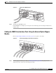
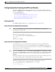
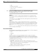
Figure 6-1 Cabling the 10GBE Interface
Step 2 Verify that the link LED is green.
If the link LED does not light, try removing the network cable plug and reinserting it firmly into the
module socket.
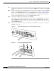
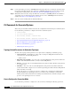
Cabling the 10GBE Line Interface Ports: Using the External Optical Bypass
Module
Refer to Optical Bypass Module Connectivity, page 6-8 for specific connectivity.
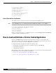
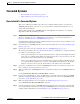
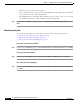
Figure 6-2 External Optical Bypass Module Line Interfaces
Step 1 Take the appropriate fiber optic cable (see Fiber Specifications, page 6-10) and plug it into the
appropriate port (A or B) on the external bypass module.
270979
SCE8000-SIP
S
TATUS
A
CTIVE/LINK
SPA-1X
1
0GE-L-V2
STAT
US
ACTIVE/LI
NK
SPA-1X
1
0GE-L-V2
270978
TX
RX
A
TX
RX
B
TX
R
X
C
TX
RX
D
A
B
A
C
C
D
B
D
S
TATUS
C
NTRL
OPB—SCE8K—MM
OPTICAL BYPASS1