
Router Installation and Configuration Guide

4-13
Cisco SCE8000 Installation and Configuration Guide, Rel 3.1.7
OL-16478-02
Chapter 4 Installing the Cisco SCE8000 Chassis
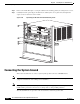
Installing the Cisco SCE8000 Chassis in the Rack
Note We recommend that you maintain a minimum air space of 6 inches (15 cm) between walls and the chassis
air vents and a minimum horizontal separation of 12 inches (30.5 cm) between two chassis to prevent
overheating.
The installation hardware is not suitable for use with racks with obstructions (such as a power strip) that
could impair access to field-replaceable units (FRUs).
Warning
To prevent bodily injury when mounting or servicing this unit in a rack, you must take special
precautions to ensure that the system remains stable. The following guidelines are provided to ensure
your safety:
>This unit should be mounted at the bottom of the rack if it is the only unit in the rack.
>When mounting this unit in a partially filled rack, load the rack from the bottom to the top with the
heaviest component at the bottom of the rack.
>If the rack is provided with stabilizing devices, install the stabilizers before mounting or servicing
the unit in the rack.
Required Tools
These tools and equipment are required to install the chassis in the rack:
• Number 1 and number 2 Phillips-head screwdrivers
• 3/16-inch flat-blade screwdriver
• Tape measure and level
• Masking tape or some other method of marking the desired installation height in the rack
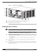
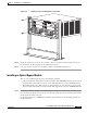
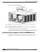
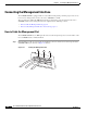
Installing the Chassis Brackets
The chassis is shipped with the mounting brackets installed on the front of the chassis. These brackets
can be installed on the rear of the chassis.
To install the brackets on the rear of the chassis, perform these steps:
Step 1 Remove the screws that secure the brackets to the chassis.