
Router Installation and Configuration Guide

9-11
Cisco SCE8000 Installation and Configuration Guide, Rel 3.1.7
OL-16478-02
Chapter 9 Removal and Replacement Procedures
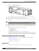
Removing and Replacing the Fan Assembly
Removing the Fan Assembly
The fan assembly is designed to be removed and replaced while the system is operating without
presenting an electrical hazard or damage to the system.
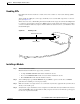
Step 1 Loosen the two captive installation screws by turning them counterclockwise.
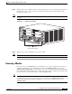
Figure 9-7 Fan Assembly
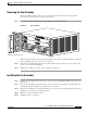
When removing the fan tray, keep your hands and fingers away from the spinning fan blades. Let the fan
blades completely stop before you remove the fan tray.
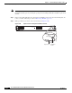
Step 2 Grasp the fan assembly with both hands and pull it outward; rock it gently if necessary to unseat the
power connector from the backplane.
Step 3 Pull the fan assembly clear of the chassis, and put it in a safe place.
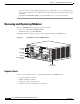
Installing the Fan Assembly
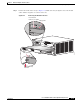
Step 1 Hold the fan assembly with the fans facing to the right and the FAN STATUS LED at the bottom. (See
Figure 9-7.)
Step 2 Place the fan assembly into the front chassis cavity so that it rests on the chassis, and then lift the fan
assembly up slightly, aligning the top and bottom chassis guides.
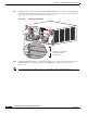
Step 3 Push the fan assembly into the chassis until the power connector seats in the backplane and the captive
installation screws make contact with the chassis.
Step 4 Tighten the captive installation screws.
Step 5 Verify that fans are operational.
270893
S
YSTE
M
P
O
W
ER
O
P
T
I
C
AL BYPA
S
S
S
TA
TUS
AUX
POR
T2
LINK
AC
TI
VE
MAST
E
R
SC
E8
0
00
E
X
T
E
N
D
ED
S
ER
VI
CE CO
N
T
R
O
L
MODUL
E
O
P
TICAL
BY
P
AS
S
OPT
ICAL
BYPASS
CO
NS
O
L
E
1
0
1
00
1
0
0
0
LINK
ACTIVE
P
O
RT
1
A
C
A
B
C
D
B
D
S
TATUS
CTR
L
OPB-SC
E
8K
-MM
OPTIC
AL
BYP
A
SS1
TX
R
X
TX
R
X
TX
RX
TX
RX
A
C
A
B
C
D
B
D
S
TATU
S
C
TR
L
OP
B-SCE8K-M
M
O
PT
ICA
L
BY
PASS 2
TX
R
X
T
X
R
X
T
X
RX
T
X
R
X
S
Y
S
TEM POW
E
R
O
P
T
I
C
A
L
BY
P
A
S
S
S
TA
TUS
A
U
X
P
O
R
T2
1
0
1
0
0
1
0
0
0
L
I
N
K
A
C
T
I
V
E
M
A
STER
SC
E8
0
0
0
E
X
T
E
N
D
ED
S
ERVIC
E CON
T
R
O
L
M
O
D
ULE
SC
E
8
0
0
0-S
C
M-
E
SC
E
8
0
0
0-S
C
M-
E
SC
E
8
0
0
0-SI
P
CO
N
S
O
L
E
1
0
100
1
0
00
L
INK
A
CTIV
E
P
O
R
T
1
O
P
T
ICAL
BYP
AS
S
O
P
T
I
CA
L
B
YP
ASS
STA
TUS
ACT
IV
E/LI
N
K
SP
A-
1
X
1
0
GE
-L
-V
2
ST
A
TU
S
A
C
TI
VE/LI
NK
SP
A-
1
X
1
0
GE-L
-
V
2
ST
A
T
US
AC
TI
V
E
/L
INK
SP
A-1
X
1
0
G
E
-L-V
2
ST
A
TU
S
A
CTI
VE
/LINK
SP
A
-1
X
1
0
G
E
-L-V
2
1
0
1
00
1
0
0
0
FAN
STATUS
Captive installation screws