
Router Installation and Configuration Guide

9-10
Cisco SCE8000 Installation and Configuration Guide, Rel 3.1.7
OL-16478-02
Chapter 9 Removal and Replacement Procedures
Removing and Replacing the Fan Assembly
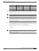
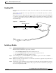
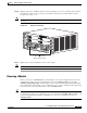
Figure 9-6 DC-Input Wires on Left Side
When installing the unit, the ground connection must always be made first and disconnected last.
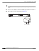
Step 8 Secure the ground cable to the cable holder with the two cable-ties.
Step 9 Retrieve the cable holder covers from the plastic bag and attach to the front panel at the locations shown
in Figure 9-3.
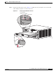
Note If the cable holder illustrated as number 5 and 8 in Figure 9-3 does not hold the DC input cables snugly,
please use a long cable tie to secure the cable holders as illustrated in number 9.
Step 10 Secure the terminal block cover using four screws and the terminal block barriers with two screws each.
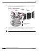
Step 11 Turn on the DC inputs and verify power supply operation by checking the power supply front panel
LEDs.
The power supply rear panel LEDs should be in the following states:
• INPUT OK LED is green
• FAN OK LED is green
• OUTPUT FAIL LED is not lit
If the LEDs indicate a power problem, see Identifying Startup Problems, page 8-6
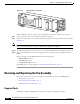
Removing and Replacing the Fan Assembly
This section describes how to remove and replace fan assemblies for the Cisco SCE8000 chassis.
• Required Tools, page 9-10
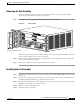
• Removing the Fan Assembly, page 9-11
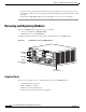
• Installing the Fan Assembly, page 9-11
Required Tools
A flat-blade or number 2 Phillips-head screwdriver is required to perform this procedure.
132220
INPUT1
OK
48V-60V
=40A
INPUT2
OK
48V-60V
=40A
FAN
OK
OUTPUT
FAIL
ALL FASTENERS MUST BE FULLY ENGAGED
PRIOR TO OPERATING THE POWER SUPPLY
PWR-2700-DC/4