
Router Installation and Configuration Guide

9-9
Cisco SCE8000 Installation and Configuration Guide, Rel 3.1.7
OL-16478-02
Chapter 9 Removal and Replacement Procedures
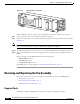
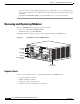
Removing and Replacing the Power Supply
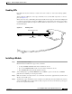
Step 6 Attach the appropriate lugs to the DC-input wires and ground wire. The wires should be sized according
to local and national installation requirements. Use only copper wire. The maximum width of a lug is
0.600 inch (15.2 mm).
Note Use fine-stranded copper conductors rated for 90-degrees Celsius for North American installations.
Note The power supply terminal block lug opening width is 0.62 inch (15.8 mm). The terminal posts are
centered 0.625 inches (15.88 mm) apart and are 1/4-20 threaded. We recommend that you use an
appropriately sized industry standard 2-hole, standard barrel compression lug. The power supply ground
studs, located below the terminal block, are also threaded 1/4-20 and require two 1/4-inch split-ring
washers and two 1/4-20 hex nuts.
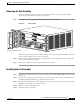
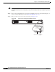
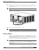
Step 7 Connect the DC-input wires to the 2700 W power supply terminal block . Depending on which side you
are connecting the DC-input wires, be sure that the DC-input wires rest in the appropriate cable holder.
The following figure shows DC-input wires coming in from the left side.
Connect the DC-input wires to the 2700 W power supply terminal block in this order:
• Ground
• Negative (-)
• Positive (+)
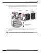
Note When you tighten the terminal nuts, make sure they are snug. Do not over tighten them. Recommended
torque strength is 20 inch-pounds. Over tightening the terminal nuts can break the terminal block
(Maximum torque: 36 inch-pounds).
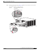
3 Status LEDs 9 Tie-wrap
4 DC power cable
terminal block cover
10 Cable holder
5 Cable holder cover 11 Tie-wrap
6 Ground