
Router Installation and Configuration Guide

9-8
Cisco SCE8000 Installation and Configuration Guide, Rel 3.1.7
OL-16478-02
Chapter 9 Removal and Replacement Procedures
Removing and Replacing the Power Supply
Step 2 Remove the plastic bag attached to the front panel and put aside. This bag contains two plastic terminal
block barriers, two cable ties, and two cable holder covers.
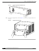
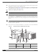
Step 3 Verify that power is off to the DC circuit connected to the power supply you are installing. Grasp both
power supply handles, as shown in Figure 9-4. Slide the power supply into the power supply bay. Make
sure that the power supply is fully seated in the bay.
Step 4 Tighten the power supply captive installation screws.
Warning
Power supply captive installation screws must be tight to ensure protective grounding continuity.
Note As the power requirement of the SCE8000 will not exceed 1350W, it is not necessary to connect two
pairs of input wires to each power supply. Should it be desired to connect two pairs of input wires, both
pairs of input wires for one 2700W DC-input power supply must come from the same battery system (A
feed); and both pairs of input wires for the other power supply must come from another battery system
(B feed).
Note For multiple DC input power supply, each DC input must be protected by dedicated circuit breaker or
fuse. The circuit breaker or fuse should be sized according to the power supply input rating and local or
national electrical code requirements.
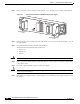
Step 5 Remove the four screws securing the terminal block cover, and slide the cover off of the terminal block.
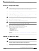
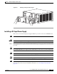
Figure 9-5 DC-Input Front Panel for 2700-W DC-Input Power Supply
132219
PWR-2700-DC/4
-VE-1
-VE-1
-VE-2
-VE-2
INPUT1
OK
48V-60V
=40A
INPUT2
OK
48V-60V
=40A
FAN
OK
OUTPUT
FAI L
ALL FASTENERS MUST BE F
ULL
Y E
NGAGED
PRIOR TO OPERA
TING THE POWER SUPPLY
3
2
6
4
10
1
8
5
7
11
9
1 Captive installation
screw
7 Cable holder cover
2 DC power cable
terminal block
8 Cable holder