
Router Installation and Configuration Guide

9-7
Cisco SCE8000 Installation and Configuration Guide, Rel 3.1.7
OL-16478-02
Chapter 9 Removal and Replacement Procedures
Removing and Replacing the Power Supply
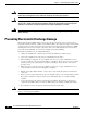
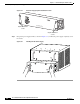
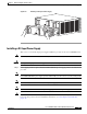
Figure 9-4 Handling a DC-Input Power Supply
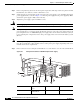
Installing a DC-Input Power Supply
This section covers the DC-input power supply installation procedure for the Cisco SCE8000 chassis.
Note The DC return is to remain isolated from the system frame and chassis (DC-I).
Warning
Before performing any of the following procedures, ensure that power is removed from the DC circuit.
Step 1 Power supply ground is required. Install the PWR-2700-DC/4 power supply ground as described in this
procedure.
Note The system ground connection with the PWR-2700-DC/4 power supply in a Cisco SCE8000 is provided
by the PWR-2700-DC/4 power supply ground. Additionally, you can connect a system (earth) ground.
Note You must always connect the PWR-2700-DC/4 power supply ground.
Note You must connect the PWR-2700-DC/4 power supply ground for both power supplies.
Note If you intend to use an additional system (earth ground), ensure that the system ground connection has
been made. For ground connection installation instructions, see Connecting the System Ground,
page 4-16.
126567
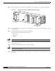
PWR-2700-DC/4
A
LL F
A
S
TE
N
E
R
S
M
U
ST B
E
FULL
Y EN
GA
G
E
D
P
R
IO
R
T
O OP
E
R
AT
IN
G
TH
E P
OW
E
R SU
PP
L
Y
INP
UT
1
OK
48V-60
V
=40A
INP
UT2
O
K
48V-6
0V
=40A
FA
N
OK
OU
TPU
T
FA
IL
-VE
-1
-VE
-1
-V
E-2
-V
E-2
AL
L
FA
ST
ENE
RS
M
U
ST
B
E
F
UL
L
Y
EN
GA
G
E
D
P
R
IO
R TO
OP
E
RA
TIN
G T
H
E P
O
W
ER
SU
P
PLY
IN
PU
T1
OK
4
8V
-60V
=40
A
INPU
T2
O
K
4
8V-6
0V
=40A
FA
N
O
K
O
UTP
U
T
FA
IL
PWR-2700-DC/4