Cisco SCE8000 Installation and Configuration Guide Release 3.1.7 December, 2008 Americas Headquarters Cisco Systems, Inc. 170 West Tasman Drive San Jose, CA 95134-1706 USA http://www.cisco.
THE SPECIFICATIONS AND INFORMATION REGARDING THE PRODUCTS IN THIS MANUAL ARE SUBJECT TO CHANGE WITHOUT NOTICE. ALL STATEMENTS, INFORMATION, AND RECOMMENDATIONS IN THIS MANUAL ARE BELIEVED TO BE ACCURATE BUT ARE PRESENTED WITHOUT WARRANTY OF ANY KIND, EXPRESS OR IMPLIED. USERS MUST TAKE FULL RESPONSIBILITY FOR THEIR APPLICATION OF ANY PRODUCTS.
C O N T E N T S About this Guide CHAPTER 1 ix Cisco Service Control Overview 1-1 Cisco Service Control Solution 1-1 Service Control for Broadband Service Providers Cisco Service Control Capabilities SCE Platform Description 1-2 1-3 Management and Collection 1-5 Network Management 1-5 Subscriber Management 1-6 Service Configuration Management Data Collection 1-6 CHAPTER 2 1-1 1-6 Introduction to the Cisco SCE8000 Platform Information About the SCE Platform 2-1 2-1 Service Control Module (SCE
Contents Cisco SCE8000 Component List Cisco SCE8000 Installation Checklist CHAPTER 3 2-14 2-15 Cisco SCE8000 Topology and Topology-Related Parameters The Cisco SCE8000 Platform Topology Considerations 3-1 3-1 3-1 Physical Topologies 3-3 SCE8000 Interface Numbering 3-3 Single Cisco SCE8000 Topologies 3-3 Single Link: Inline Topology 3-4 Dual link: Inline Installation 3-4 Single Link: Receive-only Topology 3-5 Dual Link: Receive-Only Topology 3-5 Dual Cisco SCE8000 Topology (Cascade) 3-6 Multi-Gigabi
Contents Installing the Cisco SCE8000 Chassis in the Rack 4-12 Unpacking the Cisco SCE8000 Chassis 4-12 Installation Guidelines 4-12 Required Tools 4-13 Installing the Chassis Brackets 4-13 Installing the Chassis in the Rack 4-14 Installing an Optical Bypass Module 4-15 Connecting the System Ground 4-16 Required Tools and Equipment 4-17 Installing the Power Supplies in the Cisco SCE8000 Chassis CHAPTER 5 Connecting the Management Interfaces How to Set Up the Local Console Initial Setup Parameters 5-1
Contents Cascaded Systems 6-15 How to Install a Cascaded System 6-15 CLI Commands for Cascaded Systems 6-16 Topology-Related Parameters for Redundant Topologies How to Configure the Connection Mode 6-16 How to Set the Link Mode 6-17 Monitoring the System 6-18 CHAPTER 7 Basic Cisco SCE8000 Platform Operations 6-16 7-1 Starting the Cisco SCE8000 Platform 7-1 Checking Conditions Prior to System Startup 7-1 Performing Complex Configurations 7-2 Starting the System and Observing Initial Conditions 7-2 Wha
Contents CHAPTER 8 Troubleshooting 8-1 Troubleshooting Overview 8-1 Information About Troubleshooting Tools 8-2 CLI Commands for Troubleshooting 8-2 Checking the LEDs 8-4 Problem Solving Using a Subsystems Approach 8-6 Identifying Startup Problems 8-6 Troubleshooting the Power Subsystem 8-7 Troubleshooting the Firmware Package Installation 8-8 Troubleshooting the Management Subsystem 8-8 Troubleshooting the Link Interface Subsystem 8-10 Troubleshooting with the User Log 8-11 The Logging System 8-11 How
Contents Installing a Module 9-13 Removing a Module 9-17 Inserting and Removing a Module: Detail Verifying the Installation 9-20 Removing and Replacing Shared Port Adapters Required Tools and Equipment 9-22 Laser/LED Safety 9-22 Handling SPAs 9-23 SPA Installation and Removal 9-23 Installing a SPA in a SIP 9-24 Removing a SPA from a SIP 9-24 9-19 9-22 Removing and Replacing the Optical Bypass Module 9-25 Removing the Optical Bypass Module 9-25 Installing the Optical Bypass Module 9-25 Replacing the Opti
About this Guide This preface describes who should read the Cisco SCE8000 Installation and Configuration Guide, how it is organized, and its document conventions. This guide is for the networking or computer technician responsible for installing and configuring the SCE8000 platform on-site. To use this publication, you should be familiar with telecommunications equipment and installation procedures, as well as electronic circuitry and wiring practices.
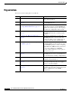
About this Guide Organization The major sections of this guide are as follows: Chapter Title Description 1 Cisco Service Control Overview, page 1-1 This chapter provides a brief introduction to Cisco Service Control. 2 Introduction to the Cisco SCE8000 Platform, This chapter provides a hardware overview of page 2-1 the SCE8000 platform.
About this Guide Related Publications Your SCE8000 platform and the software running on it contain extensive features and functionality, which are documented in the following resources: • Cisco CLI software: – Cisco SCE8000 Software Configuration Guide – Cisco SCE8000 CLI Command Reference • For initial installation and startup information, refer to the Cisco SCE8000 Quick Start Guide.
About this Guide Note Means reader take note. Tip Means the following information will help you solve a problem. Caution Timesaver Warning Means reader be careful. In this situation, you might perform an action that could result in equipment damage or loss of data. Means the described action saves time. You can save time by performing the action described in the paragraph. Means reader be warned. In this situation, you might perform an action that could result in bodily injury.
CH A P T E R 1 Cisco Service Control Overview This chapter provides a general overview of the Cisco Service Control solution. It introduces the Cisco service control concept and capabilities. It also briefly describes the hardware capabilities of the service control engine (SCE) platform and the Cisco specific applications that together compose the complete Cisco service control solution.
Chapter 1 Cisco Service Control Overview Cisco Service Control Capabilities • Report and analyze network traffic at subscriber and aggregate level for capacity planning • Provide customer-intuitive tiered application services and guarantee application service level agreements (SLAs) • Implement different service levels for different types of customers, content, or applications • Identify network abusers who are violating the acceptable use policy (AUP) • Identify and manage peer-to-peer traffic,
Chapter 1 Cisco Service Control Overview SCE Platform Description SCE Platform Description The SCE family of programmable network devices performs application-layer stateful-flow inspection of IP traffic, and controls the traffic based on configurable rules. The SCE platform is a network device that uses ASIC components and reduced instruction set computer (RISC) processors to exceed beyond packet counting and expand into the contents of network traffic.
Chapter 1 Cisco Service Control Overview SCE Platform Description Figure 1-1 SCE Platform in the Network Corporate Provider network PWR A MNG 1 LINK/ ACTIVE 10/100/ 1000 MNG 2 CONSOLE AUX LINK/ ACTIVE 10/100/ 1000 PWR B STATUS BYPASS Cisco SCE 2000 4xGBE Series LINK RX TX LINK RX TX LINK RX TX RX MM LINK RX TX TX RX MM TX RX MM TX GBE-1 SUB DSL Aggregation device LINE NET RX MM TX Users Peer network & Internet GBE-2 SUB LINE/CASCADE NET SCE platform 92764 CMTS Cisco SCE
Chapter 1 Cisco Service Control Overview Management and Collection Management and Collection The Cisco service control solution includes a complete management infrastructure that provides the following management components to manage all aspects of the solution: • Network management • Subscriber management • Service Configuration management These management interfaces are designed to comply with common management standards and to integrate easily with existing OSS infrastructure (Figure 1-2).
Chapter 1 Cisco Service Control Overview Management and Collection Subscriber Management Where the Cisco service control application for broadband (SCA BB) enforces policies on different subscribers and tracks usage on an individual subscriber basis, the Cisco service control management suite (SCMS) subscriber manager (SM) may be used as middleware software for bridging between OSS and SCE platforms.
CH A P T E R 2 Introduction to the Cisco SCE8000 Platform This chapter provides an introduction to the Cisco SCE8000 10GBE platform, the Service Control hardware component.
Chapter 2 Introduction to the Cisco SCE8000 Platform Service Control Module (SCE8000-SCM-E) Figure 2-1 FAN STA TUS SCM Cisco SCE8000 Platform SCE8000-SCM -E 1 OPTICAL BYPASS CONSOLE PORT 1 10 100 1000 STATUS OPTICAL BYPASS LINK ACTIVE SCE8000-SCM -E OPTICAL BYPASS SCM AUX 2 SCE8000 EXTENDED SERVICE PORT 2 10 100 1000 OPTICAL BYPASS CONSOLE PORT 1 10 100 1000 LINK ACTIVE CONTRO L MODULE MASTER SYSTEM POWER STATUS OPTICAL BYPASS LINK ACTIVE SCE8000-SIP OPTICAL BYPASS SIP LINK IV
Chapter 2 Introduction to the Cisco SCE8000 Platform Service Control Module (SCE8000-SCM-E) Table 2-2 SCE8000-SCM-E Ports Port Quantity Description GBE port 2 Gigabit Ethernet RJ-45 ports for A LAN using a GBE cable with an RJ-45 connector. management of the Cisco SCE8000. Currently only one GBE port is supported. CLI designation: interface GigabitEthernet 1/1, 1/2.
Chapter 2 Introduction to the Cisco SCE8000 Platform Introduction to SIPs and SPAs Table 2-3 SCE8000-SCM-E LEDs LEDs Description Master Indicates the master Service Control module Mng interface • Steady green — Master Service Control module • Unlit — Slave Service Control module The Mng interface LEDs indicate the operational status of the Cisco SCE8000 out-of-band LAN-based management port, as follows: • Link/Active Steady green — Port link is up Flashing green — Activity on the port link Un
Chapter 2 Introduction to the Cisco SCE8000 Platform Introduction to SIPs and SPAs Specifying the SIP Subslot Location for a SPA Cisco SCE8000-SIP subslots begin their numbering with “0” and have a horizontal orientation. Figure 2-3 shows the subslot numbering for the Cisco SCE8000-SIP.
Chapter 2 Introduction to the Cisco SCE8000 Platform Introduction to SIPs and SPAs Modular Optics The SPAs implement 10GBE small form-factor pluggable (XFP) optical transceivers to provide network connectivity. An XFP module is a transceiver device that mounts into the front panel to provide network connectivity. Note It is highly recommended only to use the XFP modules listed as supported in this document. Use of unsupported or unqualified XFP modules may affect reliability or operation.
Chapter 2 Introduction to the Cisco SCE8000 Platform Introduction to SIPs and SPAs The XFP operating temperature range is 0°C to 70°C.
Chapter 2 Introduction to the Cisco SCE8000 Platform The Cisco SCE8000 Optical Bypass Table 2-6 SPA Ports Port Quantity Description Connect This Port To… 10 GBE Line port 1 on each SPA Any one of the following: Any one of the following: • XFP XFP-10GLR-OC192SR (10km) • XFP-10GER-OC192IR (40km) • XFP-10GZR-OC192LR (80km) • XFP-10G-MM-SR (200m) CLI designation: interface TenGigabitEthernet 3/0/0, 3/1/0/, 3/2/0, 3/3/0.
Chapter 2 Introduction to the Cisco SCE8000 Platform The Cisco SCE8000 Optical Bypass • During a power failure —The Cisco SCE8000 has two power supplies. A power failure occurs only when both of them fail.
Chapter 2 Introduction to the Cisco SCE8000 Platform The Cisco SCE8000 Optical Bypass • OPB-SCE8K-MM supports Multi-Mode optics and should be used with SCE8000 equipped with Multi-Mode optics. The optical bypass module is installed either internally, in slot #4 of the Cisco SCE8000 chassis or in an external mounting panel in the rack. Up to two optical bypass modules can be mounted internally, supporting inline insertion into two links.
Chapter 2 Introduction to the Cisco SCE8000 Platform The Cisco SCE8000 Optical Bypass Optical Bypass Module Specifications Fiber Cable Type The fiber cable type within the Optical Bypass Module area as follows: • OPB-SCE8K-MM: 50 um core. • OPB-SCE8K-SM: SMF-28 Maximum optical path (fiber length of two ports) is 600m. Switching Time Switching time is measured from trigger to stable 90% optical output.
Chapter 2 Introduction to the Cisco SCE8000 Platform The Cisco SCE8000 Optical Bypass Power Supplies The Cisco SCE8000 platform supports redundant AC- or DC-input power supplies. The following power supplies are available for the Cisco SCE8000 platform: • 2700 W DC input (PWR-2700-DC/4): uses an external terminal block on the back side of the chassis for input power connection. • 2700 W AC input (PWR-2700-AC/4): uses an external power cord directly connected to the AC power supply.
Chapter 2 Introduction to the Cisco SCE8000 Platform Checking the Shipping Container Contents Power Supply Cooling Power supplies have built-in fans and are completely self-cooling. Air enters from the right of the fan and exits through the left. Load Sharing With two power supplies, each power supply concurrently provides approximately half of the required power to the system. If one power supply fails, the second power supply immediately assumes full power to maintain uninterrupted system operation.
Chapter 2 Introduction to the Cisco SCE8000 Platform Checking the Shipping Container Contents Cisco SCE8000 Component List Table 2-10 Cisco SCE8000 Component List Component Description Cisco SCE8000 platform Cisco SCE8000 10GBE chassis configured with the following components: Cisco SCE8000-SCM-E Cisco SCE8000 Service Control Module Cisco SCE8000-SIP Cisco SCE8000 SPA Jacket card Interface Processor 2 or 4 SPA Jacket cards SPA Interface. See below the list of supported SPA models.
Chapter 2 Introduction to the Cisco SCE8000 Platform Cisco SCE8000 Installation Checklist Cisco SCE8000 Installation Checklist To assist you with your installation and to provide a historical record of what was done by whom, photocopy the following Cisco SCE8000 Installation Checklist. Indicate when each procedure or verification is completed. When the checklist is completed, place it in your site log along with the other records for your new Cisco SCE8000 platform.
Chapter 2 Introduction to the Cisco SCE8000 Platform Cisco SCE8000 Installation Checklist Cisco SCE8000 Installation and Configuration Guide, Rel 3.1.
CH A P T E R 3 Cisco SCE8000 Topology and Topology-Related Parameters This chapter describes the possible deployment topologies of the Cisco SCE8000 and explains how to configure the relevant parameters correctly for each topology.
Chapter 3 Cisco SCE8000 Topology and Topology-Related Parameters Topology Considerations — Will the system be used solely to monitor traffic flow, with report functionality only, or will it be used for traffic flow control, with enforcement as well as report functionality? – Monitoring and Control — The Cisco SCE8000 monitors and controls traffic flow.
Chapter 3 Cisco SCE8000 Topology and Topology-Related Parameters Physical Topologies Physical Topologies Following are descriptions of a number of physical topologies that the Cisco SCE8000 supports.
Chapter 3 Cisco SCE8000 Topology and Topology-Related Parameters Physical Topologies Single Link: Inline Topology Typically, the Cisco SCE8000 is connected in a full duplex 10GBE link between two devices (Router, BRAS, etc.). When the Cisco SCE8000 is installed as an inline installation, it physically resides on the data link between the subscribers and the network.
Chapter 3 Cisco SCE8000 Topology and Topology-Related Parameters Physical Topologies Single Link: Receive-only Topology In this topology, an optical splitter resides physically on the 10GBE link between the subscribers and the network. The traffic passes through the optical splitter, which splits traffic to the Cisco SCE8000. The Cisco SCE8000, therefore, only receives traffic and does not transmit.
Chapter 3 Cisco SCE8000 Topology and Topology-Related Parameters Physical Topologies Figure 3-5 Dual Link: Receive-Only Topology Subscriber 1 Splitter 3/0/0 3/1/0 3/2/0 3/3/0 270587 Network 1 Network 2 Splitter Subscriber 2 Note When implementing receive-only topologies with a switch, the switch must support SPAN functionality that includes separation between ingress and egress traffic and multiple SPAN-ports destinations.
Chapter 3 Cisco SCE8000 Topology and Topology-Related Parameters Physical Topologies • The two Cisco SCE8000s are simultaneously aware of the subscriber contexts, and subscriber states are constantly exchanged between them, such that if the primary Cisco SCE8000 fails, the secondary can take over with minimum state loss.
Chapter 3 Cisco SCE8000 Topology and Topology-Related Parameters Physical Topologies Type of SCE Platform Redundancy • All Active All ports in the EC and all SCE platforms are active. If there is a failure in one of the SCE platforms, the links on the related ports in the EC will be down and the EC will automatically exclude it from the load distribution. The load will then be distributed between the remaining active SCE platforms.
Chapter 3 Cisco SCE8000 Topology and Topology-Related Parameters Link Continuity Link Continuity The internal bypass mechanism of the Cisco SCE8000 allows traffic to continue to flow, if desired, even if the device itself is not fully functioning. In addition, the Cisco SCE8000 is designed with the ability to control up to two external optical bypass devices (one per link). This is needed because the internal bypass mechanism cannot maintain traffic flow in all cases.
Chapter 3 Cisco SCE8000 Topology and Topology-Related Parameters Link Continuity Figure 3-9 Optical Bypass Under Normal Operating Conditions Subscriber 1 OPB Network 1 3/0/0 3/1/0 3/2/0 3/3/0 Network 2 OPB 270904 Subscriber 2 If the SCE8000 platform fails, traffic flows through the optical bypass module, bypassing the SCE8000, so that traffic on the link is maintained Figure 3-10 Optical Bypass Under Failure Conditions Subscriber 1 OPB Network 1 3/0/0 3/1/0 3/2/0 3/3/0 Network 2 Note
Chapter 3 Cisco SCE8000 Topology and Topology-Related Parameters Topology-Related Parameters Topology-Related Parameters Refer to the following sections to determine the correct values for all topology-related parameters before beginning to run the initial setup of the Cisco SCE8000.
Chapter 3 Cisco SCE8000 Topology and Topology-Related Parameters Topology-Related Parameters The connection mode parameter is determined by the physical deployment of the Cisco SCE8000, as follows: • Single Cisco SCE8000 inline installation = Inline connection mode. • Single Cisco SCE8000 optical splitter installation = Receive-only connection mode. • Two-platform cascaded Cisco SCE8000 inline installation = Inline-cascade connection mode.
Chapter 3 Cisco SCE8000 Topology and Topology-Related Parameters Asymmetric Routing Topology In a single Cisco SCE8000 topology, the value of this parameter is determined by whether or not the link can be completely cut when the Cisco SCE8000 fails, or whether traffic flow should continue across the link in spite of platform failure. In the latter case, the External-bypass mode is the recommended setting, and is therefore the default value for the on-failure mode parameter.
Chapter 3 Cisco SCE8000 Topology and Topology-Related Parameters Asymmetric Routing Topology Cisco SCE8000 Installation and Configuration Guide, Rel 3.1.
CH A P T E R 4 Installing the Cisco SCE8000 Chassis This chapter describes how to install a Cisco SCE8000 chassis. Warning Before you install, operate, or service the system, read the Regulatory Compliance and Safety Information for the Cisco SCE8000 Platform. This guide contains important safety information you should know before working with the system. Warning Only trained and qualified personnel should be allowed to install, replace, or service this equipment.
Chapter 4 Installing the Cisco SCE8000 Chassis Preparing for Installation Warning Blank faceplates and cover panels serve three important functions: they prevent exposure to hazardous voltages and currents inside the chassis; they contain electromagnetic interference (EMI) that might disrupt other equipment; and they direct the flow of cooling air through the chassis. Do not operate the system unless all cards, faceplates, front covers, and rear covers are in place.
Chapter 4 Installing the Cisco SCE8000 Chassis Preparing for Installation Preventing Electrostatic Discharge Damage Electrostatic discharge (ESD) damage, which can occur when electronic cards or components are improperly handled, results in complete or intermittent failures. Port adapters and blades consist of printed circuit boards that are fixed in metal carriers. Electromagnetic interference (EMI) shielding and connectors are integral components of the carrier.
Chapter 4 Installing the Cisco SCE8000 Chassis Preparing for Installation Follow these requirements when preparing your site for the Cisco SCE8000 installation: • The redundant power configuration provides a second, identical power supply to ensure that power to the chassis continues uninterrupted if one power supply fails or input power on one line fails. • Connect each of the two power supplies to a separate input power source.
Chapter 4 Installing the Cisco SCE8000 Chassis Preparing for Installation Table 2-5 lists the AC-input power cord options, specifications, and Cisco product numbers for the 2700 W AC-input power supplies. Table 2-5 also references power cord illustrations. Table 4-2 AC-Input Power Cord Options Locale Part Number Length Plug Rating Power Cord Reference Illustration North America (locking) CAB-GSR16-US( =) 14 feet (4.3m) 250VAC, 20A Figure 4-1 Europe CAB-GSR16-EU( =) 14 feet (4.
Chapter 4 Installing the Cisco SCE8000 Chassis Preparing for Installation AC Power Cord Illustrations This section contains the AC power cord illustrations.
Chapter 4 Installing the Cisco SCE8000 Chassis Preparing for Installation Figure 4-3 CAB-AC-2500W-EU= Cordset rating: 16 A, 250 V Length: 14 ft 0 in. (4.26 m) Plug: CEE 7/7 113360 Connector: IEC 60320 C19 Figure 4-4 CAB-AC-2500W-INT= Cordset rating: 16 A, 250 V Length: 14 ft 0 in. (4.26 m) Plug: IEC 309 113361 Connector: IEC 60320 C19 Figure 4-5 CAB-AC-2500W-ISRL= Plug: SI16S3 Cordset rating: 16 A, 250 V Length: 14 ft 0 in. (4.
Chapter 4 Installing the Cisco SCE8000 Chassis Preparing for Installation Figure 4-6 CAB-AC-2500W-US1= Plug: NEMA 6-20 Cordset rating: 16 A, 250 V Length: 14 ft 0 in. (4.26 m) 113362 Connector: IEC 60320 C19 Figure 4-7 CAB-AC-C6K-TWLK= Cordset rating: 16 A, 250 V Length: 14 ft 0 in. (4.26 m) Connector: IEC 60320 C19 113363 Plug: NEMA L6-20 Figure 4-8 CAB-7513AC= Plug: NEMA 5-20 Cordset rating: 20 A, 125 V Length: 14 ft 0 in. (4.
Chapter 4 Installing the Cisco SCE8000 Chassis Preparing for Installation Figure 4-9 CAB-7513ACSA= Cordset rating: 16 A, 250 V Length: 14 ft 0 in. (4.26 m) Plug: IEC 884 113357 Connector: IEC 60320 C19 Figure 4-10 CAB-ACS-16= Cordset rating: 16 A, 250 V Length: 8 ft 2 in. (2.5 m) Connector: IEC 60320 C19 113364 Plug: SEV 5934-2 Type 23 Figure 4-11 CAB-AC-16A-AUS Plug: AU20S3 Cordset rating: 16 A, 250 V Length: 14 ft 0 in. (4.
Chapter 4 Installing the Cisco SCE8000 Chassis Preparing for Installation Figure 4-12 CAB-C19-CBN Connector: IEC 60320 C20 Cordset rating: 16 A, 250 V Length: 9 ft 0 in. (2.7 m) Connector: IEC 60320 C19 DC-Powered Systems Basic guidelines for DC-powered systems include the following: Caution • Each chassis power supply should have its own dedicated input power source.
Chapter 4 Installing the Cisco SCE8000 Chassis Preparing for Installation Site Planning Checklist Table 2-6 lists the site planning activities that you should perform prior to installing the Cisco SCE8000 chassis. Completing each activity helps ensure a successful installation. Table 4-3 Site Planning Checklist Task No.
Chapter 4 Installing the Cisco SCE8000 Chassis Installing the Cisco SCE8000 Chassis in the Rack Installing the Cisco SCE8000 Chassis in the Rack This section describes how to install a Cisco SCE8000 platform in a rack.
Chapter 4 Installing the Cisco SCE8000 Chassis Installing the Cisco SCE8000 Chassis in the Rack Note We recommend that you maintain a minimum air space of 6 inches (15 cm) between walls and the chassis air vents and a minimum horizontal separation of 12 inches (30.5 cm) between two chassis to prevent overheating. The installation hardware is not suitable for use with racks with obstructions (such as a power strip) that could impair access to field-replaceable units (FRUs).
Chapter 4 Installing the Cisco SCE8000 Chassis Installing the Cisco SCE8000 Chassis in the Rack Figure 4-13 FAN ST ATUS SCM Brackets on Cisco SCE8000 Chassis SCE8000-SC M-E 1 OPTICAL BYPASS CONSOLE PORT 1 10 100 1000 STATUS OPTICAL BYPASS LINK ACTIVE SCE8000-SC M-E OPTICAL BYPASS SCM AUX 10 100 1000 OPTICAL BYPASS CONSOLE PORT 1 10 100 1000 SCE8000 EXTENDED SERVICE CONTROL MODULE PORT 2 2 LINK ACTIVE MASTER SYSTEM POWER STATUS OPTICAL BYPASS LINK ACTIVE SCE8000-SIP OPTICAL BYPAS
Chapter 4 Installing the Cisco SCE8000 Chassis Installing the Cisco SCE8000 Chassis in the Rack Figure 4-14 Installing the Cisco SCE8000 Chassis in the Rack FAN STA TUS SCM SCE8000-SCM -E 1 OPTICAL BYPASS CONSOLE PORT 1 10 100 1000 STATUS OPTICAL BYPASS LINK ACTIVE SCE8000-SCM -E OPTICAL BYPASS SCM SCE8000 AUX 10 100 1000 OPTICAL BYPASS CONSOLE PORT 1 10 100 1000 EXTENDED SERVICE PORT 2 2 LINK ACTIVE CONTRO L MODULE MASTER SYSTEM POWER STATUS OPTICAL BYPASS LINK ACTIVE SCE8000-S
Chapter 4 Installing the Cisco SCE8000 Chassis Connecting the System Ground Step 2 Remove the module filler plate covering the subslot in the mounting panel by loosening the two screws. Step 3 Carefully insert the optical bypass module into the subslot (there are no guide rails) and tighten the captive screws on either side of the module.
Chapter 4 Installing the Cisco SCE8000 Chassis Connecting the System Ground You must complete this procedure before connecting system power or turning on the Cisco SCE8000 chassis. Required Tools and Equipment To connect the system ground, you need the following tools and materials: Note • One grounding lug. • Two M4 (metric) hex-head screws with locking washers. The grounding lug and M4 hex-head screws with locking washers are provided in kit 69-0815-01. • One grounding wire.
Chapter 4 Installing the Cisco SCE8000 Chassis Installing the Power Supplies in the Cisco SCE8000 Chassis Figure 4-16 Installing the System Ground System ground connector Grounding lug Wire FAN ST ATUS SCM System ground connector SCE8000-SC M-E 1 OPTICAL BYPASS CONSOLE PORT 1 10 100 1000 STATUS OPTICAL BYPASS LINK ACTIVE SCE8000-SC M-E OPTICAL BYPASS SCM AUX 10 100 1000 OPTICAL BYPASS CONSOLE PORT 1 10 100 1000 SCE8000 EXTENDED SERVICE CONTROL MODULE PORT 2 2 LINK ACTIVE MASTER S
CH A P T E R 5 Connecting the Management Interfaces This chapter explains how to connect the SCE8000 Service Control Module (SCE8000-SCM-E) to a local console and perform the initial system configuration via the setup wizard that runs automatically. Additionally, this chapter contains instructions for cabling the Gigabit Ethernet Management interfaces.
Chapter 5 Connecting the Management Interfaces Initial Setup Parameters Plug the RS-232 serial cable provided with the Cisco SCE8000 into the CON port on the front panel of the SCE8000-SCM-E. (See item #2 in Figure 5-1 below.
Chapter 5 Connecting the Management Interfaces Initial Setup Parameters – Minimum length — 4 characters – Maximum length — 100 characters – Begin with an alpha character – May contain only printable characters • The default password for all levels is cisco. • System clock— Current date and time. The clock and the calendar must always be synchronized. • Time zone—The name or ID of the time zone along with the number of hours offset from UTC.
Chapter 5 Connecting the Management Interfaces Connecting the Management Interface Connecting the Management Interface The SCE8000-SCM-E is equipped with one active RJ-45 management port. This port provides access from a remote management console to the Cisco SCE8000 via a LAN. The procedures for cabling the GBE management port and testing connectivity between the Cisco SCE8000 and the remote management host are explained in the following sections.
Chapter 5 Connecting the Management Interfaces Connecting the Management Interface Step 2 Connect the other end of the Ethernet cable into your management network. Make sure that you push on the RJ-45 connector attached to the cable until you hear a click, which indicates that the connector is fully inserted and secured in the receptacle. Gently pull on the plug to confirm whether the plug is locked into the socket.
Chapter 5 Connecting the Management Interfaces Connecting the Management Interface EXAMPLE: The following example displays a typical ping response where the target IP address is 10.10.10.20. C:\>ping 10.10.10.20 pinging 10.10.10.20 ... PING 10.10.10.20: 56 data bytes 64 bytes from host (10.10.10.20): icmp_seq=0. 64 bytes from host (10.10.10.20): icmp_seq=1. 64 bytes from host (10.10.10.20): icmp_seq=2. 64 bytes from host (10.10.10.20): icmp_seq=3. ----10.10.10.
CH A P T E R 6 Cabling the Line Ports and Completing the Installation This chapter provides instructions for cabling the Cisco SCE8000 10 Gigabit Ethernet ports for single, cascaded, and MGSCP topologies. In a cascade topology, this includes the cascade ports as well as the line ports. The 10 Gigabit Ethernet ports are located on the 10G SPA modules, which are installed in the SCE8000-SIP module in slot #3 of the Cisco SCE8000 chassis.
Chapter 6 Cabling the Line Ports and Completing the Installation Connecting the Line Ports to the Network Single Link: Inline Topology In the inline topology, the Cisco SCE8000 resides physically on the 10 GBE (Ten Gigabit Ethernet) link between the subscribers and the network. The subscribers are usually connected through either a BRAS (in DSL access), a PDSN (in wireless access), a CMTS (in the Cable access), or a switch or router aggregator (in other topologies).
Chapter 6 Cabling the Line Ports and Completing the Installation Connecting the Line Ports to the Network • Dual link inline topologies require both Receive and Transmit fibers. • Dual link receive-only topologies use only Receive fibers. • To maintain link continuity at all times on both links when using the inline topology, two optical bypass modules should be installed.
Chapter 6 Cabling the Line Ports and Completing the Installation Connecting the Line Ports to the Network Multi-Gigabit Service Control Platforms (MGSCP) Topologies In this topology, multiple Cisco SCE 8000 platforms are connected to a Cisco 7600 Series router used as a load-balancer (“dispatcher”) between the platforms. Traffic enters the router, is distributed between the Cisco SCE8000 platforms by the router EtherChannel, and returns to the router to be forwarded to its original destination.
Chapter 6 Cabling the Line Ports and Completing the Installation Connecting the Line Ports to the Network The First Step-Ordering the EC Ports This section explains how to order the EC ports and assign them to links. This example is the basis for all following examples. 1. Sort the EC ports in an ascending order by their physical interface numbers. Take the following EC interfaces as an example: – EC1 (subscriber side): 0/1, 0/2, 1/3, 1/5 – EC2 (network side): 2/2, 3/1, 3/2, 3/4 2.
Chapter 6 Cabling the Line Ports and Completing the Installation Connecting the Line Ports to the Network • Link 1. S=0/1, N=2/2 • Link 2. S=0/2, N=2/4 • Link 3. S=0/3, N=3/1 • Link 4. S=1/3, N=3/2 The standby ports would be assigned to the links as follows: • Link 5 (standby). S=1/5, N=3/4 • Link 6 (standby).
Chapter 6 Cabling the Line Ports and Completing the Installation Connecting the Line Ports to the Network • Router 2: N=3/1, Cisco SCE8000 #2 3/3/0 • Router 1: S=1/3, Cisco SCE8000 #3 3/0/0 • Router 2: S=1/3, Cisco SCE8000 #3 3/2/0 • Router 1: N=3/2, Cisco SCE8000 #3 3/1/0 • Router 2: N=3/2, Cisco SCE8000 #3 3/3/0 • Router 1: S=1/5, Cisco SCE8000 #4 3/0/0 • Router 1: S=1/5, Cisco SCE8000 #4 3/2/0 • Router 1: N=3/4, Cisco SCE8000 #4 3/1/0 • Router 1: N=3/4, Cisco SCE8000 #4 3/3/0 Dual Rou
Chapter 6 Cabling the Line Ports and Completing the Installation The Optical Bypass Module • Router 1: S=0/3, Cisco SCE8000 #3 3/0/0 • Router 2: S=0/3, Cisco SCE8000 #3 3/2/0 • Router 1: N=3/1, Cisco SCE8000 #3 3/1/0 • Router 2: N=3/1, Cisco SCE8000 #3 3/3/0 • Router 1: S=1/3, Cisco SCE8000 #4 3/0/0 • Router 2: S=1/3, Cisco SCE8000 #4 3/2/0 • Router 1: N=3/2, Cisco SCE8000 #4 3/1/0 • Router 2: N=3/2, Cisco SCE8000 #4 3/3/0 • Router 1: S=1/5, Cisco SCE8000 #5 3/0/0 • Router 2: S=1/5, Ci
Chapter 6 Cabling the Line Ports and Completing the Installation Cabling the 10GBE Line Interface Ports Single Link Topology A single link requires only one bypass module. • Subscriber side network element <->Port A on the bypass module • Cisco SCE8000 port 3/0/0 <->Port C on the bypass module • Network side network element <->Port B on the bypass module • Cisco SCE8000 port 3/1/0 <->Port D on the bypass module • CTRL <->left-hand 'Optical Bypass' port on Cisco SCE8000-SCM-E module.
Chapter 6 Cabling the Line Ports and Completing the Installation Cabling the 10GBE Line Interface Ports Fiber Specifications The following table presents the fiber specifications. The Cisco SCE8000 may be ordered with either multi-mode or single mode transceivers. The transceiver type is indicated on the front panel under the ports. Note that all transceivers on any individual Cisco SCE8000 are the same mode, either 850nm multi-mode OR 1310nm single mode.
Chapter 6 Cabling the Line Ports and Completing the Installation Cabling the 10GBE Line Interface Ports Figure 6-1 Cabling the 10GBE Interface SCE8000-S IP AC T INK IVE/L S IN IVE/L ACT U AT ST K SPA-1X1 0G E-L-V2 SPA-1X1 0G E-L-V2 270979 US AT ST Step 2 Verify that the link LED is green. If the link LED does not light, try removing the network cable plug and reinserting it firmly into the module socket.
Chapter 6 Cabling the Line Ports and Completing the Installation Cabling the 10GBE Line Interface Ports Step 2 Using a cable with LC connectors on both ends, plug one end into the appropriate port (C or D) on the external bypass module and the other end into the appropriate 10GBE interface in slot #3 of the SCE8000 chassis.
Chapter 6 Cabling the Line Ports and Completing the Installation Cabling the 10GBE Line Interface Ports Testing Connectivity: Examining Link LEDs and Counters If the Cisco SCE8000 platform has been powered up, test now to verify that connectivity has been established on all links. If the Cisco SCE8000 platform is not powered up, perform this step after starting the Cisco SCE8000 platform.
Chapter 6 Cabling the Line Ports and Completing the Installation How to Load and Activate a Service Control Application In good multicast packets: 0 In good broadcast packets: 10 In packets discarded: 0 In packets with CRC/Alignment error: 0 In undersized packets: 0 In oversized packets: 0 Out total octets: 93*2^32+1022342538 Out unicast packets: 858086051 Out non unicast packets: 0 Out packets discarded: 0 How to View the User Log Counters You should view the user log for errors that occurred during th
Chapter 6 Cabling the Line Ports and Completing the Installation Cascaded Systems Cascaded Systems • How to Install a Cascaded System, page 6-15 • CLI Commands for Cascaded Systems, page 6-16 How to Install a Cascaded System This section outlines the installation procedures for a redundant solution with two cascaded Cisco SCE8000 platforms. Refer to the Cisco Service Control Engine (SCE) CLI Command Reference for details of the CLI commands.
Chapter 6 Cabling the Line Ports and Completing the Installation Cascaded Systems Step 9 Connect the traffic port of Cisco SCE8000 platform #2. This will cause a momentary down time until the network elements from both sides of the Cisco SCE8000 platform auto-negotiate with it and start working (when working inline). (See Dual Link: Two Cisco SCE8000s Topology, page 6-3.) Step 10 When full control is needed, change the link mode on both Cisco SCE8000 platforms on both links to ‘forwarding’.
Chapter 6 Cabling the Line Ports and Completing the Installation Cascaded Systems Step 1 • inline • physically connected links • behavior upon failure of the SCE platform • primary/secondary From the Cisco SCE8000(config if)# prompt, type connection-mode inline-cascade physically-connected-links (link-0|link-1) priority (primary|secondary) on-failure (external-bypass|bypass|cutoff) and press Enter.
Chapter 6 Cabling the Line Ports and Completing the Installation Cascaded Systems Step 1 • Link mode is relevant only to inline topologies. • It is recommended that in cascaded topologies, both SCE platforms be configured for the same link mode, otherwise the service will be unpredictable. • The default link mode is forwarding. When other link modes are selected, active service control is not available and any service control configuration will not be applicable.
CH A P T E R 7 Basic Cisco SCE8000 Platform Operations This chapter describes how to start up the Cisco SCE8000 platform, reboot, and shutdown. It also describes how to manage configurations.
Chapter 7 Basic Cisco SCE8000 Platform Operations Starting the Cisco SCE8000 Platform – Direct connection to local console (CON port) – Remote management station via the LAN (Mng port) Performing Complex Configurations After you have installed your Cisco SCE8000 platform hardware, checked all external connections, turned on the system power, allowed the system to boot up, and performed the initial system configuration, you might need to perform more complex configurations, which are beyond the scope of
Chapter 7 Basic Cisco SCE8000 Platform Operations Starting the Cisco SCE8000 Platform Final Tests The procedures for performing the final tests to verify that the Cisco SCE8000 is functioning properly are explained in the following sections: • Verifying Operational Status, page 7-3 • Viewing the User Log Counters, page 7-3 • Viewing the Ten Gigabit Ethernet Port Status, page 7-4 • Viewing the Ten Gigabit Ethernet Counters, page 7-4 Verifying Operational Status After all the ports are connected, ve
Chapter 7 Basic Cisco SCE8000 Platform Operations Starting the Cisco SCE8000 Platform Viewing the Ten Gigabit Ethernet Port Status Step 1 At the Cisco SCE8000# prompt, type show interface TenGigabitEthernet 3/ baynumber /0. This displays the port link status. The following example displays a system response.
Chapter 7 Basic Cisco SCE8000 Platform Operations Managing Cisco SCE8000 Configurations Managing Cisco SCE8000 Configurations After you have installed your SCE8000 platform hardware, checked all external connections, turned on the system power, and allowed the system to boot up, you are ready to install the Service Control application. However, before you install the application, you might need to configure the SCE platform.
Chapter 7 Basic Cisco SCE8000 Platform Operations Managing Cisco SCE8000 Configurations RDR-formatter destination 10.56.96.26 port 33000 category number 4 priority 100 interface LineCard 0 connection-mode inline on-failure external-bypass no silent no shutdown attack-filter subscriber-notification ports 80 replace spare-memory code bytes 3145728 interface GigabitEthernet 1/1 ip address 10.56.96.46 255.255.252.
Chapter 7 Basic Cisco SCE8000 Platform Operations Managing Cisco SCE8000 Configurations Step 2 Check the displayed configuration to make sure that it is set the way you want. If not, make the changes you want before saving. Step 3 Type copy running-config startup-config. The system saves all running configuration information to the configuration file, which is used when the system reboots. The configuration file holds all information that is different from the system default in a file called config.
Chapter 7 Basic Cisco SCE8000 Platform Operations Managing Cisco SCE8000 Configurations management-agent property "com.pcube.management.framework.install.activated.version" "3.1.6 build 79" management-agent property "com.pcube.management.framework.install.activation.
Chapter 7 Basic Cisco SCE8000 Platform Operations How to Display the SCE Platform Version Information RDR-formatter forwarding-mode multicast RDR-formatter destination 10.56.96.26 port 33000 category RDR-formatter destination 10.56.96.26 port 33000 category RDR-formatter destination 10.56.96.26 port 33000 category RDR-formatter destination 10.56.96.
Chapter 7 Basic Cisco SCE8000 Platform Operations How to Display the SCE Platform Version Information SCE>show version System version: Version 3.1.6S Build 279 Build time: Jun 10 2008, 19:27:47 (Change-list 335658) Software version is: Version 3.1.6S Build 279 Hardware information is: ---------------Firmware ---------------kernel : [kernel] 1.0.0/5 (inactive: [kernel] 1.0.0/5) u-boot : [uboot] 1.0.0/6 (field: [uboot] 0.8.1/13) select : [ubs-cf1] 1.0.0/5 (secondary: [ubs-cf1] 1.0.
Chapter 7 Basic Cisco SCE8000 Platform Operations How to Display the SCE Platform Version Information #cpus : 3 cpu-0 SVR : 0x80900121 cpu-0 PVR : 0x80040202 cpu-0 freq : 1500MHz cpu-1 SVR : 0x80900121 cpu-1 PVR : 0x80040202 cpu-1 freq : 1500MHz cpu-2 SVR : 0x80900121 cpu-2 PVR : 0x80040202 cpu-2 freq : 1500MHz cpu (eeprom): 2.
Chapter 7 Basic Cisco SCE8000 Platform Operations How to Display the SCE Platform Inventory How to Display the SCE Platform Inventory Unique Device Identification (UDI) is a Cisco baseline feature that is supported by all Cisco platforms. This feature allows network administrators to remotely manage the assets in their network by tracing specific devices through either CLI or SNMP.
Chapter 7 Basic Cisco SCE8000 Platform Operations How to Display the SCE Platform Inventory NAME: "SPA-1X10GE-L-V2", DESCR: "SPA-1X10GE-L-V2" PID: SPA-1X10GE-L-V2 , VID: V02, SN: JAE115295HH NAME: "SCE8000 FAN 1", DESCR: "FAN-MOD-4HS" PID: FAN-MOD-4HS , VID: V0 , SN: DCH11013744 NAME: "SCE8000 AC or DC power supply 0", DESCR: "PWR-2700-AC/4" PID: PWR-2700-AC/4 , VID: V0 , SN: APQ105000MV NAME: "SCE8000 AC or DC power supply 1", DESCR: "PWR-2700-AC/4" PID: PWR-2700-AC/4 , VID: V0 , SN: APQ105000MV NAME: "X
Chapter 7 Basic Cisco SCE8000 Platform Operations How to Display the SCE Platform Inventory NAME: "SCE8000 SPA Interface Processor (SIP) in slot 3", DESCR: "SCE8000-SIP" PID: SCE8000-SIP , VID: V01, SN: CAT1150G07F NAME: "SCE8000 Link 0", DESCR: "SCE8000 Link" PID: "" , VID: "" , SN: "" NAME: "SCE8000 Link 1", DESCR: "SCE8000 Link" PID: "" , VID: "" , SN: "" NAME: "SCE8000 SIP bay 3/0", DESCR: "SCE8000 SIP bay" PID: "" , VID: "" , SN: "" NAME: "SCE8000 SIP bay 3/1", DESCR: "SCE8000 SIP bay" PID: "" , VID
Chapter 7 Basic Cisco SCE8000 Platform Operations How to Display the SCE Platform Inventory NAME: "SCE8000 optic 3/3/0", DESCR: "XFP-10GLR-OC192SR " PID: XFP-10GLR-OC192SR , VID: V02, SN: AGA1143N4JN NAME: "SCE8000 traffic processor 1", DESCR: "SCE8000 traffic processor" PID: "" , VID: "" , SN: "" NAME: "SCE8000 traffic processor 2", DESCR: "SCE8000 traffic processor" PID: "" , VID: "" , SN: "" NAME: "SCE8000 traffic processor 3", DESCR: "SCE8000 traffic processor" PID: "" , VID: "" , SN: "" NAME: "SCE800
Chapter 7 Basic Cisco SCE8000 Platform Operations How to Display the System Uptime How to Display the System Uptime Use this command to see how long the system has been running since the last reboot. Step 1 At the SCE> prompt, type show system-uptime and press Enter. Example for Displaying the System Uptime The following example shows how to display the system uptime of the SCE platform.
Chapter 7 Basic Cisco SCE8000 Platform Operations Rebooting and Shutting Down the SCE Platform How to Shut Down the SCE Platform Shutting down the SCE platform is required before turning the power off. This helps to ensure that non-volatile memory devices in the SCE platform are properly flushed in an orderly manner. Note When the SCE platform restarts, it loads the startup configuration, so all changes made in the running configuration will be lost.
Chapter 7 Basic Cisco SCE8000 Platform Operations Rebooting and Shutting Down the SCE Platform Cisco SCE8000 Installation and Configuration Guide, Rel 3.1.
CH A P T E R 8 Troubleshooting Your Cisco SCE8000 platform went through extensive testing before leaving the factory. However, if you encounter problems starting it, use the information in this chapter to help isolate the cause of the problems. The procedures in this chapter assume that you are troubleshooting the initial system startup, and that your Cisco SCE8000 platform is in the original factory configuration.
Chapter 8 Troubleshooting Troubleshooting Overview . Table 8-1 Troubleshooting Strategy for Startup Problems Action Step 1 Turn power on. Go to Step 2 Step 2 Check the following: • Front panel power LED on? • Power supply 'Input OK' LEDs on? • 'Output fail' LEDs not on? Yes No Go to Step 3 Refer to Troubleshooting the Power Subsystem, page 8-7 and go to Step 3. Step 3 Status LED red (failure) Refer to Troubleshooting the Firmware Package Installation, page 8-8 and go to Step 4.
Chapter 8 Troubleshooting Troubleshooting Overview SCE(config)#boot system ftp://cisco:cisco@10.10.10.10/downloads/SENum.pkg.pkg Verifying package file SENum.pkg.pkg… Package file verified OK. • Troubleshooting the management subsystem: – show interface GigabitEthernet 1/1 — Displays IP address and auto-negotiation information for the management interfaces. Following is a sample output from the show interface GigabitEthernet 1/1 command. ip address: 10.1.6.145 subnet mask: 255.255.0.
Chapter 8 Troubleshooting Troubleshooting Overview L2 In total octets: 792000 In good unicast packets: 12000 In good multicast packets: 0 In good broadcast packets: 0 In packets discarded: 0 In packets with CRC/Alignment error: 0 In undersized packets: 0 In oversized packets: 0 Rx pause packets: 0 L2 Out total octets: 0 Out unicast packets: 0 Out good multicast packets: 0 Out good broadcast packets: 0 Out packets discarded: 0 Tx pause packets: 0 Tx regular collision events: 0 L2 Bandwidth Kbps (Rx + Tx):
Chapter 8 Troubleshooting Troubleshooting Overview Cisco SCE8000 Operational Status The following table lists the operational states of the Cisco SCE8000. The Status LED on the Service Control module reflects the current Cisco SCE8000 operational status. Once boot is complete, the operational status can be displayed using CLI command show system operation-status .
Chapter 8 Troubleshooting Troubleshooting Overview Table 8-3 Power Supply LEDs LED Label Color State Function INPUT OK Green On The input voltage is present and within the required range. Off The input voltage is not present or not within the required range. On The output voltage is not within the required range. Off The output voltage is in the required range. On Power supply internal fan is operational. Off Power supply internal fan is not operational.
Chapter 8 Troubleshooting Troubleshooting Overview • If the Status LED is flashing orange, indicating a warning state, check the user log: At the prompt, type: more user log If any of the following warning messages appear, and the root cause is not obvious and easily solved (such as obstruction of external air-flow) turn the Cisco SCE8000 platform off and call technical support.
Chapter 8 Troubleshooting Troubleshooting Overview Troubleshooting the Firmware Package Installation Check the following to help isolate a problem in the installation of the firmware package. Problems related to the installation of the firmware package could be any of the following: • File not found in the expected location • Wrong file type. • Device to which the file is to be extracted is full.
Chapter 8 Troubleshooting Troubleshooting Overview .
Chapter 8 Troubleshooting Troubleshooting Overview Table 8-7 Symptom Troubleshooting the Management Subsystem Diagnostic Action Telnet connection terminates automatically Possible Cause Possible Solution CLI command: show ip route Routing tables are incorrectly configured (when the host used as client is not in the same network as the SCE Platform, and there is more than one gateway on the SCE Platform network). Check / reconfigure routing tables.
Chapter 8 Troubleshooting Troubleshooting with the User Log Table 8-8 Symptom • Link is down. (LINK LED not lit) • Output counters not incrementing. Troubleshooting the Link Interface Subsystem Diagnostic Action Possible Cause Possible Solution CLI command: Connector is not connected to the platform or to the network. Reconnect the fiber to the 10GBE port and to network. Fiber is broken or damaged. Reconnect / replace the fiber to the 10GBE port.
Chapter 8 Troubleshooting Troubleshooting with the User Log • How to Copy the User Log to an External Source, page 8-12 • How to Copy the User Log to an Internal Location, page 8-12 • How to View the User Log, page 8-12 • How to Clear the User Log, page 8-12 • How to View the User Log Counters, page 8-13 • How to View the Non-volatile Counter For the User-file-log Only, page 8-13 How to Copy the User Log to an External Source You can view the log file by copying it to an external source.
Chapter 8 Troubleshooting Troubleshooting with the User Log How to View the User Log Counters There are two types of log counters: Step 1 • User log counters — count the number of system events logged from the SCE platform last reboot. • Non-volatile counters — are not cleared during boot time From the SCE# prompt, type show logger device user-file-log counters and press Enter.
Chapter 8 Troubleshooting Troubleshooting with the User Log Cisco SCE8000 Installation and Configuration Guide, Rel 3.1.
CH A P T E R 9 Removal and Replacement Procedures This chapter describes how to perform removal and replacement procedures for Cisco SCE8000 platform field-replaceable units (FRUs). Warning Before you install, operate, or service the system, read the Regulatory Compliance and Safety Information for the Cisco SCE8000 . This guide contains important safety information you should know before working with the system.
Chapter 9 Removal and Replacement Procedures Preventing Electrostatic Discharge Damage Warning Because invisible laser radiation may be emitted from the aperture of the port when no cable is connected, avoid exposure to laser radiation and do not stare into open apertures. Warning This equipment must be grounded. Never defeat the ground conductor or operate the equipment in the absence of a suitably installed ground conductor.
Chapter 9 Removal and Replacement Procedures Supported Hardware Supported Hardware The Cisco SCE8000 platform supports the following hardware: • One Service Control Module (SCE8000-SCM-E), with an optional redundant Service Control Module (FRU). • One SPA jacket module (SCE8000-SIP), with either two or four SPA 10GBE interface modules (all FRU). • Up to two optical bypass modules installed in the bottom slot of the chassis.
Chapter 9 Removal and Replacement Procedures Removing and Replacing the Power Supply Figure 9-1 AC Power Supply Captive Installation Screws PWR-AC 100-240 V-16A 50/60Hz INPUT OK ALL FA ST PRIOR ENERS MU ST TO OP ERATING BE FULLY ENGA THE PO WER SU GED PPLY 126565 Captive installation screws FAN OU TPUT OK FAIL Captive installation screws Step 5 Grasp both power supply handles, as shown in Figure 9-2, and slide the power supply completely out of the chassis.
Chapter 9 Removal and Replacement Procedures Removing and Replacing the Power Supply Installing an AC-Input Power Supply Warning This product requires short-circuit (over current) protection, to be provided as part of the building installation. Install only in accordance with national and local wiring regulations. Step 1 Ensure that the system (earth) ground connection has been made.
Chapter 9 Removal and Replacement Procedures Removing and Replacing the Power Supply Step 2 Remove the four screws securing the terminal block cover, and slide the cover off the terminal block.
Chapter 9 Removal and Replacement Procedures Removing and Replacing the Power Supply Figure 9-4 Handling a DC-Input Power Supply PWR-27 00-DC/ 4 INPUT1 INPUT2 OK FAN OUT PUT 48V-60V OK 48V-60V OK FAIL =40A =40A ALL FAST PRIOR ENERS MUS TO OPE T RATING BE FULLY ENG THE POW AGE ER SUPP D LY PWR-27 00-DC/ 126567 4 -VE-1 -VE-1 INPUT1 INPUT2 OK FAN OUT PUT 48V-60V OK 48V-60V OK FAIL =40A =40A -VE-2 -VE-2 ALL FAST PRIOR ENERS MUS TO OPE T RATING BE FULLY ENG THE POW AGE ER SUPP D LY Installing
Chapter 9 Removal and Replacement Procedures Removing and Replacing the Power Supply Step 2 Remove the plastic bag attached to the front panel and put aside. This bag contains two plastic terminal block barriers, two cable ties, and two cable holder covers. Step 3 Verify that power is off to the DC circuit connected to the power supply you are installing. Grasp both power supply handles, as shown in Figure 9-4. Slide the power supply into the power supply bay.
Chapter 9 Removal and Replacement Procedures Removing and Replacing the Power Supply Step 6 3 Status LEDs 9 Tie-wrap 4 DC power cable terminal block cover 10 Cable holder 5 Cable holder cover 11 Tie-wrap 6 Ground Attach the appropriate lugs to the DC-input wires and ground wire. The wires should be sized according to local and national installation requirements. Use only copper wire. The maximum width of a lug is 0.600 inch (15.2 mm).
Chapter 9 Removal and Replacement Procedures Removing and Replacing the Fan Assembly Figure 9-6 DC-Input Wires on Left Side PWR-2 700-DC /4 ALL FA ST PRIOR ENERS MU ST TO OP ERATING BE FULLY ENGA THE PO WER SU GED PPLY 132220 INPUT 1 INPUT 2 FA OK N OUTP 48V-60V OK UT 48V-60V OK FAIL =40A =40A When installing the unit, the ground connection must always be made first and disconnected last. Step 8 Secure the ground cable to the cable holder with the two cable-ties.
Chapter 9 Removal and Replacement Procedures Removing and Replacing the Fan Assembly Removing the Fan Assembly The fan assembly is designed to be removed and replaced while the system is operating without presenting an electrical hazard or damage to the system. Step 1 Loosen the two captive installation screws by turning them counterclockwise.
Chapter 9 Removal and Replacement Procedures Removing and Replacing Modules • Listen for the fans; you should immediately hear them operating. If you do not hear them, ensure that the fan assembly is inserted completely in the chassis and the faceplate is flush with the switch back panel. • Verify that the FAN STATUS LED is green. If the LED is red, one or more fans is faulty.
Chapter 9 Removal and Replacement Procedures Removing and Replacing Modules Handling SIPs Each SIP circuit board is mounted to a metal carrier and is sensitive to electrostatic discharge (ESD) damage. Always handle the SIP by the carrier edges and handle; never touch the SIP components or connector pins. (See Figure 9-9.
Chapter 9 Removal and Replacement Procedures Removing and Replacing Modules Note If the captive installation screws are loose, the EMI gaskets on the installed modules will push adjacent modules toward the open slot, reducing the opening size and making it difficult to install the replacement module. Step 5 Remove the module filler plate by removing the two Phillips pan-head screws from the filler plate.
Chapter 9 Removal and Replacement Procedures Removing and Replacing Modules Step 7 Position the module in the slot. (See Figure 9-11.) Make sure that you align the sides of the module carrier with the slot guides on each side of the slot.
Chapter 9 Removal and Replacement Procedures Removing and Replacing Modules Step 8 Carefully slide the module into the slot until the EMI gasket along the top edge of the module makes contact with the module in the slot above it and both ejector levers have closed to approximately 45 degrees with respect to the module faceplate. (See Figure 9-12.
Chapter 9 Removal and Replacement Procedures Removing and Replacing Modules Step 10 While pressing down, simultaneously close the left and right ejector levers to fully seat the module in the backplane connector. The ejector levers are fully closed when they are flush with the module faceplate. (See Figure 9-13) Note Failure to fully seat the module in the backplane connector can result in incorrect operation and/or error messages.
Chapter 9 Removal and Replacement Procedures Removing and Replacing Modules Step 1 At the SCE# prompt, type reload shutdown and press Enter to power down the Cisco SCE8000 platform before installing or removing any module. Step 2 Verify that the captive installation screws on all of the modules in the chassis are tight. This step assures that the space created by the removed module is maintained.
Chapter 9 Removal and Replacement Procedures Removing and Replacing Modules Inserting and Removing a Module: Detail Refer to the following illustrations for detailed views of: • A captive screw • The ejector lever • The slot guide Figure 9-14 A Module Installation and Removal SCE8000SCM-E FAN STA TUS SCM SCE8000-SCM-E 1 OPTICAL BYPASS CONSOLE PORT 1 10 100 1000 STATUS OPTICAL BYPASS LINK ACTIVE SCE8000-SCM-E SCE8000-SCM-E SCM OPTICAL BYPASS AUX PORT 2 2 10 100 1000 OPTICAL BYPASS
Chapter 9 Removal and Replacement Procedures Removing and Replacing Modules Verifying the Installation Use the show version command to verify that the system software and firmware are installed properly. Step 1 From the SCE>prompt, type show version and press Enter. This example shows the output of the show version command: System version: Version 3.1.6S Build 279 Build time: Jun 10 2008, 19:27:47 (Change-list 335658) Software version is: Version 3.1.
Chapter 9 Removal and Replacement Procedures Removing and Replacing Modules cpld-1-ufm : 0xb803 cpld-2-ufm : 0xb803 summit-0 : 0x1000a summit-1 : 0x1000a fc : 0x1044 ---------------CFC-1 ---------------board type : P2 #cpus : 3 cpu-0 SVR : 0x80900121 cpu-0 PVR : 0x80040202 cpu-0 freq : 1500MHz cpu-1 SVR : 0x80900121 cpu-1 PVR : 0x80040202 cpu-1 freq : 1500MHz cpu-2 SVR : 0x80900121 cpu-2 PVR : 0x80040202 cpu-2 freq : 1500MHz cpu (eeprom): 2.
Chapter 9 Removal and Replacement Procedures Removing and Replacing Shared Port Adapters After you verify installation of an SCE8000 module and check connectivity, you must configure the module. For complete information on configuring the Cisco SCE8000 platform, refer to the Cisco SCE8000 Software Configuration Guide. For information on all Cisco SCE8000 platform commands, refer to the Cisco SCE8000 CLI Command Reference publication.
Chapter 9 Removal and Replacement Procedures Removing and Replacing Shared Port Adapters Figure 9-15 Class 1 Laser Warning Labels for SPA Ports CLASS 1 LASER PRODUCT LASERPRODUKT DER KLASSE 1 PRODUIT LASER DE CLASSE 1 1 PRODUCTO LASER CLASE 1 Warning Class 1 laser product. Statement 1008 Warning Invisible laser radiation may be emitted from disconnected fibers or connectors. Do not stare into beams or view directly with optical instruments. Statement 1051 Warning Class 1 LED product.
Chapter 9 Removal and Replacement Procedures Removing and Replacing Shared Port Adapters SPAs can be inserted or removed independently from the SIP. Removal of a SIP with installed SPAs is also supported. Figure 9-17 illustrates how to install and remove a SPA in the SCE8000-SIP. Figure 9-17 SPA Installation and Removal 7600-S IP-400 270988 1 0 S TU A ST SPA INTE PROCES RFACE SOR 2 AT ST SPA-1X1 0GE-L-V US 2 US AT ST SPA-1X1 0GE-L-V 2 2 This number...
Chapter 9 Removal and Replacement Procedures Removing and Replacing the Optical Bypass Module Step 3 To remove the SPA from the SIP, unfasten the captive installation screws on the SPA. Step 4 Grasp the handles of the SPA and pull the SPA from the SIP.
Chapter 9 Removal and Replacement Procedures Removing and Replacing the Optical Bypass Module Replacing the Optical Bypass Module without Disrupting Traffic on the Link You can replace a malfunctioning SCE8000 platform without disrupting traffic on the link by removing the optical bypass modules while still connected to the network and installing them into the new SCE8000. Step 1 Install the new SCE8000 platform in the rack. Power up the platform and perform necessary initial configuration.
A P P E N D I X A Using Optical Splitters with 10GBE Links • Supported Configurations, page A-1 • Unsupported Configuration, page A-2 When designing a deployment with the SCE8000, it is important to keep in mind certain characteristics of the 10GBE link that affect the configuration of optical splitters and SPAN ports. • Ten Gigabit Ethernet does not support autonegotiation (unlike regular GBE).
Appendix A Subscriber Supported SPAN Port Configuration Switch RX TX Note 3/0/0 3/1/0 3/2/0 3/3/0 Network 270986 Figure A-2 Using Optical Splitters with 10GBE Links In the above configuration, it is essential that the SCE8000 be operating in receive-only mode. Other configurations may cause SPAN port traffic to be returned to the switch, causing unpredictable behavior.