ADMINISTRATION GUIDE Cisco Small Business RV0xx Series Routers RV042 Dual WAN VPN Router RV042G Gigabit Dual WAN VPN Router RV082 Dual WAN VPN Router RV016 Multi-WAN VPN Router
Cisco and the Cisco logo are trademarks or registered trademarks of Cisco and/or its affiliates in the U.S. and other countries. To view a list of Cisco trademarks, go to this URL: www.cisco.com/go/trademarks. Third-party trademarks mentioned are the property of their respective owners. The use of the word partner does not imply a partnership relationship between Cisco and any other company. (1110R) © 2011-2012 Cisco Systems, Inc. All rights reserved.
Contents Chapter 1: Introduction RV0xx Series Router Features Ports 7 7 9 Status Lights 10 Other Hardware Features 11 Default Settings 12 Mounting Options 12 Placement Tips 12 Desktop Placement 12 Wall Mounting 13 Rack Mounting RV082 or RV016 14 Connecting the Equipment 15 Getting Started with the Configuration 16 Troubleshooting Tips 17 Features of the User Interface 18 Chapter 2: Viewing System Summary Information 20 Chapter 3: Setup 26 Setting Up the Network 27 Changing th
Contents Chapter 4: DHCP 63 Setting Up the DHCP Server or DHCP Relay 63 Viewing the DHCP Status Information 70 Router Advertisement (IPv6) 71 Chapter 5: System Management 73 Setting Up Dual WAN and Multi-WAN Connections 73 Managing the Bandwidth Settings 81 Setting Up SNMP 84 Enabling Device Discovery with Bonjour 85 Using Built-In Diagnostic Tools 87 Restoring the Factory Default Settings 89 Upgrading the Firmware 90 Restarting the Router 91 Backing Up and Restoring the Settings
Contents Updating the ProtectLink License Chapter 9: VPN 120 122 Introduction to VPNs 122 Site to Site VPN (Gateway To Gateway) 123 Remote Access (Client To Gateway) 123 Remote Access with Cisco QuickVPN 125 Remote Access with PPTP 125 Viewing the Summary Information for VPN 126 Setting Up a Gateway to Gateway (Site to Site) VPN 130 Setting Up a Remote Access Tunnel for VPN Clients (Client To Gateway) 139 Managing VPN Users and Certificates 147 Setting Up VPN Passthrough 149 Setting Up
Contents Appendix D: Configuring a Gateway-to-Gateway VPN Tunnel Between RV0xx Series Routers 170 Topology Options 170 VPN Hub and Spoke Topology 171 VPN Mesh Topology 172 Other Design Considerations 173 Configuring a VPN Tunnel on a Cisco RV0xx Series Router 175 Example: Sites with Static WAN IP Addresses 176 Example: Site with a Dynamic WAN IP Address 179 Appendix E: IPSec NAT Traversal Overview Appendix F: Bandwidth Management 183 183 186 Creation of New Services 186 Creation of New
1 Introduction Thank you for choosing a RV0xx Series VPN Router. This guide provides complete information to help you configure and manage your router. This chapter includes information to help you get started using your router.
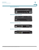
1 Introduction RV0xx Series Router Features RV042 and RV042G Ports 2 3 4 Internet DMZ/Internet 278823 1 RV042 and RV042G Status Lights System DIAG Internet DMZ/ DMZMode Internet 1 2 3 4 278822 Cisco Small Business RV042 RV082 Ports and Status Lights DIAG Internet System DMZ Internet DMZ Mode 1 2 3 4 5 6 7 8 2 3 4 Cisco Small Business RV082 DMZ/Internet 5 6 7 Internet 10/100 16-Port VPN Router 8 278824 1 RV016 Ports and Status Lights DIAG 1 2 3 4 5 9 10
1 Introduction RV0xx Series Router Features Ports Port Description Internet (RV042 and RV082) or Internet 1-2 (RV016) Use this port to connect the router to a broadband network device. DMZ/Internet (RV042 and RV082) Use this port to connect the router to either a second broadband network device or a DMZ host such as a web server or FTP server. A DMZ allows public Internet traffic to access a specified computer on your network without exposing your LAN.
1 Introduction RV0xx Series Router Features Status Lights Light Description DIAG Lit—The router is preparing for use. Unlit— The router is ready for use. System Steady—The router is powered on. Flashing—The router is running a diagnostic test. Internet (RV082, RV042, RV042G) or Internet 1-2 (RV016) Steady—A device is connected to the Internet port. Flashing—There is network activity over the Internet port.
1 Introduction RV0xx Series Router Features Other Hardware Features Feature Description Reset The Reset button is an indented black button. On the back panel of the RV042 and RV042G, look for this button near the port labeled 1. On the front panel of the RV082 and RV016, look for this button near the Internet and DMZ ports .
1 Introduction Mounting Options Default Settings Parameter Username Password LAN IP DHCP Range Netmask Default Value admin admin 192.168.1.1 192.168.1.100 to 149 255.255.255.0 Mounting Options Placement Tips • Ambient Temperature—To prevent the router from overheating, do not operate it in an area that exceeds an ambient temperature of 104°F (40°C). • Air Flow—Be sure that there is adequate air flow around the router.
1 Introduction Mounting Options Wall Mounting The router has two wall-mount slots on the bottom panel. To mount the router on a wall, you need mounting hardware (not included). Suggested hardware is illustrated below (not true to scale). Suggested Hardware for RV042 and RV042G 5-5.5 mm 20-22 mm Suggested Hardware for RV082 and RV016 6.5-7 mm 16.5-18.5 mm WARNING Insecure mounting might damage the router or cause injury. Cisco is not responsible for damages incurred by insecure wall-mounting.
1 Introduction Mounting Options STEP 2 Insert a screw into each hole, leaving a gap between the surface and the base of the screw head of 1 to 1.2 mm. STEP 3 Place the router wall-mount slots over the screws and slide the router down until the screws fit snugly into the wall-mount slots. Rack Mounting RV082 or RV016 You can mount the RV082 or RV016 in a standard size, 19-inch (about 48 cm) wide rack. The router requires 1 rack unit (RU) of space, which is 1.75 inches (44.45mm) high.
1 Introduction Connecting the Equipment Connecting the Equipment STEP 1 Make sure that all network devices are powered off, including the router, PCs, Ethernet switches, and broadband network device (DSL or cable modem). STEP 2 To connect to your Internet service: • RV042, RV042G, and RV082: Connect an Ethernet cable from the broadband network device to the Internet port of the router.
Introduction Getting Started with the Configuration • 1 RV016: Connect an Ethernet cable from the Internet 2 port to a second broadband network device. STEP 4 To connect a computer or server that will be a DMZ host: • RV042, RV042G, and RV082: Connect an Ethernet cable from the DMZ/ Internet port to the DMZ host. • RV016: Connect an Ethernet cable from the DMZ port to the DMZ host.
Introduction Getting Started with the Configuration 1 STEP 6 To use the setup wizard to configure your Internet connection, click Setup Wizard on the System Summary page, or click Wizard in the navigation tree. In the Basic Setup section, click Launch Now. Follow the on-screen instructions. If your web browser displays a warning message about the pop-up window, allow the blocked content. STEP 7 To configure other settings, use the links in the navigation tree.
1 Introduction Features of the User Interface Features of the User Interface The user interface is designed to make it easy for you to set up and manage your router. Refer to these topics: • Navigation, page 18 • Pop-Up Windows, page 19 • Setup Wizards, page 19 • Saving the Settings, page 19 • Help, page 19 • Logout, page 19 Navigation The major modules of the configuration utility are represented by buttons in the left navigation pane. Click a button to view more options.
1 Introduction Features of the User Interface Pop-Up Windows Some links and buttons launch pop-up windows that display more information or related configuration pages. If your web browser displays a warning message about the pop-up window, allow the blocked content. Setup Wizards Two setup wizards make it easy to set up your Internet connection and/or DMZ and to configure access rules for the WAN, LAN, and DMZ. You can use these wizards or use the other pages of the configuration utility.
2 Viewing System Summary Information The System Summary page appears after you log in to the configuration utility. You also can view this page by clicking System Summary in the navigation tree. Use this page to view information about the current status of the router and the settings.
Viewing System Summary Information 2 System Information This section includes the following information: • Serial Number: The serial number of the router. • Firmware version: The current version number of the firmware installed on the router. • PID VID: The current version number of the hardware. • MD5 Checksum: A value used for file validation. • LAN IP / Subnet mask: The current IP Address of the router on the local network. • Working Mode: The working mode (Gateway or Router).
Viewing System Summary Information 2 Configuration If you need help to configure the router, click Setup Wizard. You can then use these wizards: • Basic Setup Wizard: Use this wizard to set up your Internet connection. • Access Rule Setup Wizard: Use this Wizard to set up the security policy for your VPN. Port Statistics This table shows the status and available statistics for each port. It also provides access to detailed information about current link activity. • Port ID: The port label.
Viewing System Summary Information 2 This window displays the following information: - Type: The type of port, 10Base-T/100 Base-TX. - Interface: The type of interface, such as LAN, DMZ, or WAN. - Link Status: The current status of the link: Up or Down. - Port Activity: The current activity on the port, either Port Enabled, Port Disabled, or Port Connected. - Priority: The priority setting, High or Normal. - Speed Status: The speed, 10Mbps or 100Mbps.
Viewing System Summary Information 2 - Auto negotiation: The auto negotiation setting, On or Off. - VLAN: The VLAN ID. - Receive Packet Count: The number of packets received through this port. - Receive Packet Byte Count: The number of bytes received through this port. - Transmit Packet Count: The number of packets transmitted through this port. - Transmit Packet Byte Count: The number of bytes transmitted through this port. - Packet Error Count: The number of packet errors.
Viewing System Summary Information • 2 DMZ information: - IP Address: The current public IP address for this interface. - DMZ Host: The DMZ private IP address of the DMZ host. The default is Disabled. Firewall Setting Status This section displays the following information: • SPI (Stateful Packet Inspection): The status of this feature: On (green) or Off (red). • DoS (Denial of Service): The status of this feature, On (green) or Off (red).
3 Setup Use the Setup module to set up the basic functions of the router.
3 Setup Setting Up the Network Setting Up the Network Use the Setup > Network page to set up your LAN, WAN (Internet connections), and DMZ interface. To open this page: Click Setup > Network in the navigation tree. NOTE Before navigating away from this page, click Save to save your settings, or click Cancel to undo them. Any unsaved changes are abandoned.
3 Setup Setting Up the Network IP Mode Choose the type of addressing to use on your network: • IPv4 Only—Use only IPv4 addressing. • Dual-Stack IP—Use IPv4 and IPv6 addressing. After you enable this option by saving the settings on this page, you can configure both IPv4 and IPv6 addresses for LAN, WAN, and DMZ settings on this page.
3 Setup Setting Up the Network After you click Save, a pop-up window displays a reminder that you will need to use the new device IP address to launch the configuration utility. Click OK to close the message and continue with the IP address change, or click Cancel to close the message without applying the changes. STEP 3 Release and renew the IP address of your PC. You should then receive a new IP address in the new DHCP range for the router.
3 Setup Setting Up the Network STEP 3 In the pop-up window, add or edit entries as needed. • To add a new subnet: Enter a LAN IP Address and a Subnet Mask. Click Add to list. The IP address and subnet mask appear in the list. Repeat this step as needed to add other subnets. Examples: - Two subnets: If the router has a LAN IP address of 192.168.1.1 with a subnet mask of 255.255.255.0, you could set up a second subnet with a LAN IP address of 192.168.2.1 and a subnet mask of 255.255.255.0.
3 Setup Setting Up the Network STEP 4 When you finish entering settings in the Multiple Subnet window, click OK to save your changes, or click Cancel to undo them. WAN Setting (Internet connection) The router is pre-configured with default settings that are sufficient for many networks. However, special settings may be required by your ISP (Internet Service Provider) or broadband (DSL or cable) carrier. Refer to the setup information provided by your ISP.
3 Setup Setting Up the Network • To modify the WAN settings: If you have any unsaved changes on the Network page, click Save to save your settings before continuing. For the interface that you want to modify, click the Edit icon to open the Edit WAN Connection page. For more information, see Editing a WAN Connection, page 34. DMZ Setting On Cisco RV042, RV042G, and RV082, you can configure the Internet/DMZ port for use as a DMZ (De-Militarized Zone or De-Marcation Zone).
3 Setup Setting Up the Network • To edit DMZ settings: Click the Edit icon to open the Edit DMZ Connection page. For more information, see Editing a DMZ Connection, page 38. If you have not saved your settings, a warning appears. Click OK to save your settings, or click Cancel to close the window without saving.
3 Editing a WAN Connection Editing a WAN Connection with IPv4 Addressing Editing a WAN Connection with IPv6 Addressing The Edit WAN Connection page appears after you click an Edit icon in the WAN Settings section of the Network page. Enter the information provided by your ISP. NOTE Before navigating away from this page, click Save to save your settings, or click Cancel to undo them. Any unsaved changes are abandoned. • Interface: The selected WAN port appears. This ID cannot be changed.
3 the Following DNS Server Addresses box. Then enter an IP address in the DNS Server (Required) 1 box. Optionally, you can enter a second DNS server. The first available DNS entry is used. - Static IP: Choose this option if your ISP assigned a permanent IP address to your account. Then enter the settings provided by your ISP: Specify WAN IP Address: The external IP address that your ISP assigned to your account. Subnet Mask (IPv4): The subnet mask specified by your ISP.
3 - PPTP (Point-to-Point Tunneling Protocol): Choose this option if required by your ISP. PPTP is a service used in Europe, Israel, and other countries. Specify WAN IP Address: The external IP address that your ISP assigned to your account. Subnet Mask: The subnet mask specified by your ISP. Default Gateway Address: The IP address of the default gateway. Username and Password: Enter the username and password for your ISP account. The maximum number of characters is 60.
3 • MTU: Set the MTU (Maximum Transmission Unit) in bytes (see the Glossary). Unless a change is required by your ISP, Cisco recommends that you use the default setting, Auto. To specify another value, select Manual, and then enter the size in bytes. • Enabled DHCP-PD: Check this box to enable the DHCPv6 client process and enable a request for prefix delegation through the selected interface. This option is typically used if your ISP is capable of sending LAN prefixes via DHCPv6 option.
3 Editing a DMZ Connection Use the Edit DMZ Connection page to specify the settings for your DMZ. DMZ is enabled by default. IPv4 IPv6 The Edit DMZ Connection page appears after you click the Edit icon in the DMZ Setting section of the Network page. NOTE Before navigating away from this page, click Save to save your settings, or click Cancel to undo them. Any unsaved changes are abandoned.
3 If you are using IPv6 addressing, enter the following information: • Specify DMZ IPv6 Address: Enter an IPv6 address for the DMZ. Replace the default double colon (::) with a valid IPv6 address for your DMZ. • Prefix Length: Enter the prefix length. The default value is 64.
Setup Changing the Administrator Username and Password 3 Changing the Administrator Username and Password Use the Setup > Password page to update the administrator username and password. You can keep the default username (admin) if you like. However, Cisco strongly recommends changing the default password (admin) to a strong password that is hard to guess. ! CAUTION The password cannot be recovered if it is lost or forgotten.
Setup Changing the Administrator Username and Password 3 • Confirm New Username: To confirm, re-enter the new username, exactly as shown in the previous field. • New Password: Enter a new password for the router. You can include alphanumeric characters and symbols, but no spaces. • Confirm New Password: To confirm, re-enter the new password, exactly as shown in the previous field. An error message appears if the passwords do not match.
3 Setup Setting the System Time Setting the System Time Use the Setup > Time page to specify the system time for your network. The router uses the time settings to time-stamp log events, to automatically apply the Access Rules and Content Filters, and to perform other activities for other internal purposes. You can allow the router to receive the local time settings automatically from a server, or you can enter the local time manually. To open this page: Click Setup > Time in the navigation tree.
3 Setup Setting Up a DMZ Host • Set the local time Manually: Choose this option if you want to set the local time yourself. Then enter the following information: - Date: Enter the current date in yyyy.mm.dd format, such as 2010.06.25 for June 25, 2010. - Hours, Minutes, Seconds: Enter the current time in hh:mm:ss format, such as 15:17:00 for 3:17:00 p.m.
Setup Setting Up Port Forwarding and Port Triggering 3 Setting Up Port Forwarding and Port Triggering Use the Setup > Forwarding page if you need to allow public access to services on computers that are connected to the LAN ports. Port Forwarding opens a specified port or a port range for a service, such as FTP. Port Triggering opens a port range for services such as Internet gaming that use alternate ports to communicate between the server and LAN host.
Setup Setting Up Port Forwarding and Port Triggering • 3 To add an entry to the list: Enter the following information, and then click Add to list. - Service: Select the service. If a service is not listed, you can add a service. For details, see Adding a service, page 46. - IP Address: Enter the LAN IP address of the server that you want the Internet users to access. - Enable: Check the box to enable this port range forwarding entry.
Setup Setting Up Port Forwarding and Port Triggering 3 Adding a service To add a new entry to the Service list, or to change an entry that you created previously, click Service Management. If the web browser displays a warning about the pop-up window, allow the blocked content. In the Service Management window, add or update entries as needed. Before closing this window, click OK to save your settings, or click Cancel to undo them. Any unsaved changes are abandoned.
Setup Setting Up Port Forwarding and Port Triggering 3 • To modify a service you created: Click the service in the list. The information appears in the text fields. Make the changes, and then click Update. If you do not need to make changes, you can click Add New to deselect the service and clear the text fields. • To delete a service from the list: Click the entry that you want to delete.
Setup Setting Up Universal Plug and Play (UPnP) 3 • To delete an entry from the list: Click the entry that you want to delete, and then click Delete. To select a block of entries, click the first entry, hold down the Shift key, and then click the final entry in the block. To select individual entries, press the Ctrl key while clicking each entry. To de-select an entry, press the Ctrl key while clicking the entry. • To view the port range table: Click View, near the bottom of the page.
Setup Setting Up Universal Plug and Play (UPnP) 3 To enable UPnP, click Yes. To disable this feature, click No. Add or edit entries as needed. • To add an entry to the list: Enter the following information, and then click Add to List. You can have up to 30 services in the list. - Service: Select the service. If a service is not listed, you can add a service. See Adding a service, page 50. - Name or IP Address: Enter the name or IP address of the UPnP device.
Setup Setting Up Universal Plug and Play (UPnP) 3 Adding a service To add a new entry to the Service list, or to change an entry that you created previously, click Service Management. If the web browser displays a warning about the pop-up window, allow the blocked content. In the Service Management window, add or update entries as needed. Before closing this window, click OK to save your settings, or click Cancel to undo them. Any unsaved changes are abandoned.
3 Setup Setting Up One-to-One NAT • To modify a service you created: Click the service in the list. The information appears in the text fields. Make the changes, and then click Update. If you do not need to make changes, you can click Add New to deselect the service and clear the text fields. • To delete a service from the list: Click the entry that you want to delete. To select a block of entries, click the first entry, hold down the Shift key, and click the final entry in the block.
3 Setup Setting Up One-to-One NAT NOTE Before navigating away from this page, click Save to save your settings, or click Cancel to undo them. Any unsaved changes are abandoned. To enable this feature, check the Enable One-to-One NAT box. Add or edit entries as needed. • To add an entry to the list: Enter the following information, and then click Add to List. - Private Range Begin: Enter the starting IP address of the internal IP address range that you want to map to the public range.
Setup Cloning a MAC Address for the Router 3 Cloning a MAC Address for the Router Some ISPs require that you register a MAC address, which is a 12-digit code assigned to a unique piece of hardware for identification. If you previously registered another MAC address with your ISP, you can use the Setup > MAC Address Clone page to “clone” that address to your Cisco RV0xx Series router. By using this process, you don’t have to call your ISP to change the registered MAC address.
3 Editing the MAC Address Clone Settings The Edit MAC Address Clone page appears after you click the Edit icon on the MAC Address Clone page. NOTE Before navigating away from this page, click Save to save your settings, or click Cancel to undo them. Any unsaved changes are abandoned. To clone a MAC address, enter the following settings.
Assigning a Dynamic DNS Host Name to a WAN Interface 3 Assigning a Dynamic DNS Host Name to a WAN Interface Dynamic Domain Name System (DDNS) service allows you to assign a fixed domain name to a dynamic WAN IP address, so you can host your own web, FTP or other type of TCP/IP server in your LAN. Use the Setup > Dynamic DNS page to configure the WAN interfaces with your Dynamic DNS information. Before configuring Dynamic DNS on the router, you need to visit www.dyndns.org and register a domain name.
3 Editing the Dynamic DNS Setup The Edit Dynamic DNS Setup page appears after you click an Edit icon on the Dynamic DNS page. NOTE Before navigating away from this page, click Save to save your settings, or click Cancel to undo them. Any unsaved changes are abandoned. From the DDNS Service list, choose your service. Then enter the information for your account, as described below. To disable this feature, choose Disable. • Username: Enter the username for your DDNS account.
3 Setting Up Advanced Routing Setting Up Advanced Routing Use the Setup > Advanced Routing page to configure the dynamic and static routing settings and to view current routing information. To open this page: Click Setup > Advanced Routing in the navigation tree. NOTE Before navigating away from this page, click Save to save your settings, or click Cancel to undo them. Any unsaved changes are abandoned.
3 Setting Up Advanced Routing Configuring Dynamic Routing Enter the settings for dynamic routing by using Routing Information Protocol (RIP) (see the glossary for more information). Dynamic Routing for IPv4: Click the IPv4 tab, and then enter the settings described below. • Working Mode: Choose one of the following options. - Gateway: Choose this mode if the router is hosting your network’s connection to the Internet. This is the default setting.
3 Setting Up Advanced Routing Dynamic Routing for IPv6: NOTE The IPv6 tab is available if you enabled Dual-Stack IP on the Setup > Network page. Check the box to enable RIPng (RIP next generation), or uncheck the box to disable it. (See the Glossary for more information.) Configuring Static Routing Enter the settings for static routing (see the Glossary for more information). WARNING Static routing is an advanced feature. Create these routes with care. Add or edit entries as needed.
3 Setting Up Advanced Routing • To add another new static route: Enter the information, and then click Add to list. • To modify a static route in the list: Click the entry that you want to modify. The information appears in the text fields. Make the changes, and then click Update. If you do not need to make changes, you can click Add New to deselect the entry and clear the text fields. • To delete an entry from the list: Click the entry that you want to delete, and then click Delete.
3 IPv6 Transition IPv6 Transition When Dual-Stack IP is enabled on the Network > Setup page, a 6to4 tunnel is enabled by default for IPv6 packets via 6to4 source/destination addressing exchange. This feature allows the router to establish auto-tunnel in IPv4 network (or a real IPv4 Internet connection) across two independent IPv6 networks. Use the Setup > IPv6 Transition page to disable or enable this feature. To open this page: Click Setup > IPv6 Transition in the navigation tree.
3 IPv6 Transition address or a range of addresses on the local network and the destination is a single IP address or a range of addresses on the remote network. • Complete the required tasks on the router at the other end of the 6to4 tunnel. NOTE For detailed application notes, see the documentation links in Appendix H, “Where to Go From Here.
4 DHCP Use the DHCP module to configure the settings for the DHCP server or DHCP relay agent, and to view DHCP summary information. If Dual-Stack IP is enabled on the Network > Setup page, you can configure IPv4 and IPv6 settings.
DHCP Setting Up the DHCP Server or DHCP Relay 4 To open this page: Click DHCP > DHCP Setup in the navigation tree. NOTE Before navigating away from this page, click Save to save your settings, or click Cancel to undo them. Any unsaved changes are abandoned. Enabling DHCP Server and DHCP Relay Click the IPv4 tab or the IPv6 tab. Note: The IPv6 tab is available only if you enabled Dual-Stack IP on the Network > Setup page.
DHCP Setting Up the DHCP Server or DHCP Relay 4 NOTE IPv4 only: If you disable both DHCP server and DHCP Relay, configure each device on your network with a static IP address, subnet mask, and DNS settings. Do not assign the same IP address to different computers. Dynamic IP (used for DHCP Server only) • Client Lease Time: The Client Lease Time is the amount of time that a network user is allowed to connect to the router with the current dynamic IP address. Enter the amount of time in minutes.
DHCP Setting Up the DHCP Server or DHCP Relay 4 About Static IP Addresses (for IPv4 Only) When DHCP is enabled, you may wish to assign static IP addresses to certain devices, such as a web server or an FTP server. You can add up to 100 devices to the Static IP list. TIP Ensure that each of these devices is configured to use a static IP address. For example, on a Windows computer, open the Local Area Connection Properties, select Internet Protocol (TCP/IP), and then click the Properties button.
DHCP Setting Up the DHCP Server or DHCP Relay 4 The devices are listed by the IP address and the MAC address. (Typically the MAC address appears on a label on the bottom panel or back panel of a device.) If needed, you can click Refresh to update the data. STEP 2 To select a device, first enter a descriptive Name. Then check the Enable box. Alternatively, select all devices in the list by clicking the check box at the top of the Enable column.
DHCP Setting Up the DHCP Server or DHCP Relay 4 • To modify the settings: Click a device in the list. The information appears in the text fields. Make the changes, and then click Update. If you do not need to make changes, you can click Add New to de-select the entry and clear the text fields. • To delete an entry from the list: Click the entry that you want to delete, and then click Delete.
DHCP Setting Up the DHCP Server or DHCP Relay 4 DNS Local Database Domain Name Service (DNS) is a service that matches a domain name to its routable IP address. You can set up a DNS Local Database that enables the router to act as a local DNS server for commonly used domain names. Using a local database may be faster than using an external DNS server.
DHCP Viewing the DHCP Status Information 4 Viewing the DHCP Status Information Use the DHCP > Status page to view the status of the DHCP server and its clients. You can click Refresh to refresh the data. To release a client’s IP address, you can click the Delete icon. To open this page: Click DHCP > DHCP Status in the navigation tree.
4 DHCP Router Advertisement (IPv6) • MAC Address (IPv4 only): The MAC address of a client. • Client Lease Time: The amount of time that a network user can remain connected to the router with a dynamic IP address. • Delete (IPv4 only): Click the icon to delete the lease and disconnect the client. Router Advertisement (IPv6) Use the DHCP > Router Advertisement page to enable the RADVD (Router Advertisement Daemon) for IPv6 auto-configuration and routing.
4 DHCP Router Advertisement (IPv6) • RA Flags: Choose whether or not hosts can use DHCPv6 to obtain addresses and other information. The options are described below. - Enabling the Managed flag only: Check the Managed box if you want hosts to use an administered /stateful configuration protocol (DHCPv6) to obtain stateful addresses and other information through DHCPv6.
5 System Management Use the System Management module to manage advanced settings, to configure diagnostic tools, and to perform tasks such as firmware upgrades, backups, and reboots.
System Management Setting Up Dual WAN and Multi-WAN Connections 5 Mode - Cisco RV042, RV042G, and RV082 You can configure up to two Internet connections by using the Internet port and the DMZ/Internet port. You can choose one of the following modes to manage your WAN connections: • Smart Link Backup: Choose this mode to ensure continuous connectivity. If the primary WAN connection is unavailable, the backup WAN connection is used.
System Management Setting Up Dual WAN and Multi-WAN Connections 5 Mode - Cisco RV016 You can configure up to seven Internet connections by using the two Internet ports and the five dual-function ports. You can choose one of the following modes to manage your WAN connections: • Intelligent Balancer (Auto Mode): Select this option to balance traffic between all interfaces to increase the available bandwidth. The router balances the traffic between the interfaces in a weighted round robin fashion.
System Management Setting Up Dual WAN and Multi-WAN Connections 5 Interface Setting Click the Edit icon for the interface that you want to set up. Then enter the settings on the Edit Dual WAN settings page. For more information, see Editing the Dual WAN and Multi-WAN Settings, page 77. NOTE If there are unsaved changes on the Dual WAN page, a warning appears. You can click OK to close the message. Then click Save to save your changes. After saving your changes, click the Edit icon.
5 Editing the Dual WAN and Multi-WAN Settings The Dual WAN Settings page (Multi-WAN Settings on RV016) appears after you click the Edit icon for a WAN interface on the Dual WAN (or Multi-WAN) page. Enter the interface settings, as needed. NOTE Before navigating away from this page, click Save to save your settings, or click Cancel to undo them. Any unsaved changes are abandoned.
5 records the failure in the System Log. There is no failover to the other interface. If you choose Remove the Connection, failover occurs and the backup interface is used. When the WAN port’s connectivity is restored, its traffic is restored. • Default Gateway, ISP Host, Remote Host, and DNS Lookup Host: Check the box for each device that you want to ping to determine network connectivity. For an ISP host or a remote host, enter the IP address. For a DNS Lookup host, enter a host name or domain name.
5 • To delete an entry from the list: Click the entry that you want to delete, and then click Delete. To select a block of entries, click the first entry, hold down the Shift key, and then click the final entry in the block. To select individual entries, press the Ctrl key while clicking each entry. To de-select an entry, press the Ctrl key while clicking the entry. Adding a service To add a new entry to the Service list, or to change an entry that you created previously, click Service Management.
5 - To add another new service: Enter the information, and then click Add to list. - To modify a service you created: Click the service in the list. The information appears in the text fields. Make the changes, and then click Update. If you do not need to make changes, you can click Add New to de-select the service and clear the text fields. - To delete a service from the list: Click the entry that you want to delete.
5 Managing the Bandwidth Settings Managing the Bandwidth Settings Use the System Management > Bandwidth Management page to adjust the bandwidth settings for upstream and downstream traffic and to configure Quality of Service (QoS) settings for various types of traffic. For example, you can enter bandwidth rules to ensure quality for voice services. For a detailed example, see Appendix F, “Bandwidth Management.” To open this page: Click System Management > Bandwidth Management in the navigation tree.
5 Managing the Bandwidth Settings • Priority: Choose this option to manage the bandwidth by identifying highpriority and low-priority services. Select an Interface. Add the services that are subject to bandwidth management. • To add a new service to the list: Enter the settings as described below, and then click Add to List. You can add up to 100 services. - Service: Select a service to manage. If a service is not listed, you can click Service Management to add a service.
5 Managing the Bandwidth Settings Adding a service To add a new entry to the Service list, or to change an entry that you created previously, click Service Management. If the web browser displays a warning about the pop-up window, allow the blocked content. In the Service Management window, add or update entries as needed. Before closing this window, click OK to save your settings, or click Cancel to undo them. Any unsaved changes are abandoned.
5 Setting Up SNMP • To modify a service you created: Click the service in the list. The information appears in the text fields. Make the changes, and then click Update. If you do not need to make changes, you can click Add New to deselect the service and clear the text fields. • To delete a service from the list: Click the entry that you want to delete. To select a block of entries, click the first entry, hold down the Shift key, and click the final entry in the block.
Enabling Device Discovery with Bonjour 5 • Enabled SNMP: Check this box to enable SNMP. Uncheck the box to disable the this feature. This feature is enabled by default. • System Name: Set the hostname for the router. • System Contact: Enter the name of the network administrator who can be contacted with updates about the router. • System Location: Enter the network administrator’s contact information: an e-mail address, telephone number, or pager number.
Enabling Device Discovery with Bonjour 5 NOTE For discovery of Cisco Small Business products, Cisco provides a utility that works through a simple toolbar on the web browser. This utility discovers Cisco devices in the network and display basic information, such as serial numbers and IP addresses, to aid in the configuration and deployment. For more information and to download the utility, please visit www.cisco.com/go/findit.
Using Built-In Diagnostic Tools 5 Using Built-In Diagnostic Tools Use the System Management > Diagnostic page to access two built-in tools, DNS Name Lookup and Ping. If you suspect a problem with connectivity, you can use these tools to investigate. To open this page: Click System Management > Diagnostic. Choose DNS Name Lookup if you know a DNS name and want to learn the IP address. Choose Ping to test the connectivity to a particular IP address on the Internet.
5 Using Built-In Diagnostic Tools Ping Choose this option to test connectivity to a specified host by entering the IP address. If you do not know the IP address, use the DNS Lookup tool to learn it. The ping test shows if the router is able to send a packet to a remote host and receive a response. If users on the LAN are having problems accessing services on the Internet, first try pinging your DNS server or other server at your ISP. If this test is successful, try pinging devices outside the ISP.
Restoring the Factory Default Settings 5 Restoring the Factory Default Settings Use the System Management > Factory Default page to clear all of your configuration information and restore the router to its factory default settings. Only use this feature if you want to discard all the settings and preferences that you have configured. To open this page: Click System Management > Factory Default in the navigation tree.
5 Upgrading the Firmware Upgrading the Firmware Use the System Management > Firmware Upgrade page to download the latest firmware for your router and to install it. WARNING If you choose an earlier firmware version, the factory default settings will be used. All custom settings. WARNING Upgrading firmware may take several minutes. Do not turn off the power, press the reset button, close the browser, or disconnect the link during this process.
5 Restarting the Router • To download the latest firmware from Cisco: Click Firmware Download from Web Site.Your web browser opens the router information page on Cisco.com. Click the Download Firmware button. Continue through the screens to select the latest router firmware and to download the file. Extract the file on your computer. Then perform the firmware upgrade as described above. Restarting the Router If you need to restart the router, Cisco recommends that you use the Restart tool on this page.
Backing Up and Restoring the Settings 5 Backing Up and Restoring the Settings Use the System Management > Backup and Restore page to import, export, and copy your configuration files. The router has two configuration files: the startup and the mirror. The Startup file is the configuration file that the router loads when it boots up. The router automatically copies the startup file to the mirror. Thus, the Mirror file contains the last known valid configuration.
Backing Up and Restoring the Settings 5 STEP 1 In the Restore Startup Configuration File section, click Browse. STEP 2 Select a configuration file (.config). STEP 3 Click Restore. This process may take up to a minute. STEP 4 Click System Management > Restart in the navigation tree. STEP 5 When the confirmation message appears, click OK. If you do not want to restart the router, click Cancel. The imported settings are not applied until you restart the router.
Backing Up and Restoring the Settings 5 • If a setting is changed, the time counter resets, and the next automatic copy will occur 24 hours later. • If the mirror config file is still in its factory default state, copying the mirror to the startup immediately resets the router to the factory default settings. To copy a file, click the button: • Copy Startup to Mirror: Click this button to replace the mirror file with the startup file.
6 Port Management Use the Port Management module to configure port settings and view the port status. • Configuring the Port Settings, page 95 • Viewing the Status Information for a Port, page 97 Configuring the Port Settings The default port settings should be sufficient for most small businesses, but you can use the Port Management > Port Setup page to customize these settings if needed. You can disable a port or customize its priority, speed, duplex mode, and auto-negotiation settings.
6 Port Management Configuring the Port Settings For Cisco RV016 only, choose the number of WAN ports from the drop-down list, or keep the default number, 2. If you change the number, save your settings. (You can also change the number of WAN ports by using the Setup > Network page.
Port Management Viewing the Status Information for a Port 6 Viewing the Status Information for a Port Use the Port Management > Port Status page to view information and statistics for a selected port. To open this page: Click Port Management > Port Status in the navigation tree. From the Port ID list, choose a port. You can click Refresh to update the data.
Port Management Viewing the Status Information for a Port 6 Statistics For the selected port, the Statistics table displays the following: • Port Receive Packet Count: The number of packets received • Port Receive Packet Byte Count: The number of packet bytes received • Port Transmit Packet Count: The number of packets transmitted • Port Transmit Packet Byte Count: The number of packet bytes transmitted • Port Packet Error Count: The number of packet errors Cisco Small Business RV0xx Series Rout
7 Firewall Use the Firewall module to configure the firewall features, create access rules, and set content filters to control your users’ Internet activities. Refer to these topics: • Configuring the General Firewall Settings, page 99 • Managing Access Rules, page 104 • Configuring Firewall Access Rules, page 103 • Using Content Filters to Control Internet Access, page 110 Configuring the General Firewall Settings The default firewall settings should be sufficient for most small businesses.
Firewall Configuring the General Firewall Settings 7 NOTE • If you want to disable the firewall (not recommended), you can do so only if you have configured the administrator password. If you are still using the default password, you must change it. For more information, see Changing the Administrator Username and Password, page 40. • Before navigating away from this page, click Save to save your settings, or click Cancel to undo them. Any unsaved changes are abandoned.
Firewall Configuring the General Firewall Settings 7 default Port setting, 80, or enter another port number (8080 is usually used for this purpose). NOTE: When remote management is enabled, you can use a web browser to access the configuration utility from anywhere on the Internet. In a web browser, enter http://:port, or enter https://:port if you have enabled the HTTPS feature. • HTTPS: When enabled, this feature allows secured HTTP sessions.
Firewall Configuring the General Firewall Settings 7 sites (see Don’t block Java/Java/ActiveX/Cookies/Proxy to Trusted Domains below). By default, ActiveX is not blocked. • Access to HTTP Proxy Servers: Check this box if you want to block access to HTTP proxy servers. Use of WAN proxy servers may compromise the router’s security. If you enable this feature, you block access to proxy servers using port 80 or 8080.
7 Firewall Configuring Firewall Access Rules Configuring Firewall Access Rules The default access rules should be sufficient for most small businesses. However, you can use the Firewall > Access Rules page to modify or add new access rules for your network. Access rules determine which traffic is allowed to pass through the router’s firewall. Optionally, you can set a schedule to activate or deactivate each access rule for specified days and times.
7 Firewall Configuring Firewall Access Rules • All traffic from the WAN to the DMZ is allowed. • All traffic from the DMZ to the WAN is allowed. ! CAUTION With the use of custom rules, it is possible to disable all firewall protection or block all access to the Internet, so use extreme caution when creating or deleting access rules.
7 Firewall Configuring Firewall Access Rules priority rule takes precedence. The default access rules have the lowest priority. When an access rule is created, the router automatically assigns a priority; however, you can change the priority after the rule is created. • Enable: To enable a rule, check the Enable box. To disable a rule, uncheck the box. You cannot change the default rules.
7 Configuring Access Rules After you click Add New Rule or the Edit icon on the Access Rules table, enter the following information on the add/edit page. NOTE Before navigating away from this page, click Save to save your settings. When the Success message appears, click OK to remain on the current page to add another access rule, or click Cancel to return to the Access Rules table. To undo your changes on this page, click Cancel. Any unsaved changes are abandoned.
7 • - Range: This rule applies to a range of IP addresses (IPv4 only). Enter the first IP address of the range in the first box, and then enter the final IP address in the second box. - Subnet: This rule applies to a subnetwork (IPv6 only). Enter the IP address and the prefix length. - ANY: This rule applies to any IP address. Destination IP (IPv4) or Destination IP / Prefix Length (IPv6): Identify the destination of the traffic that is affected by this rule.
7 Adding a service To add a new entry to the Service list, or to change an entry that you created previously, click Service Management. If the web browser displays a warning about the pop-up window, allow the blocked content. In the Service Management window, add or update entries as needed. Before closing this window, click OK to save your settings, or click Cancel to undo them. Any unsaved changes are abandoned.
7 • To modify a service you created: Click the service in the list. The information appears in the text fields. Make the changes, and then click Update. If you do not need to make changes, you can click Add New to deselect the service and clear the text fields. • To delete a service from the list: Click the entry that you want to delete. To select a block of entries, click the first entry, hold down the Shift key, and click the final entry in the block.
Using Content Filters to Control Internet Access 7 Using Content Filters to Control Internet Access Use the Firewall > Content Filter page to prevent your users from accessing inappropriate websites. You can block access by specifying domains and keywords. To open this page: Click Firewall > Content Filter in the navigation tree. NOTE Before navigating away from this page, click Save to save your settings, or click Cancel to undo them. Any unsaved changes are abandoned.
Using Content Filters to Control Internet Access 7 Forbidden Domains Check the Enable Block Forbidden Domains box to allow the router to block access to specified domains. Uncheck the box to disable this feature. Add or edit rules as needed. Remember that your entries are not saved until you click the Save button. • To add an entry to the list: Type the domain name in the Add box. Then click Add to list. Repeat this task as needed to add other domains.
Using Content Filters to Control Internet Access • 7 To delete an entry from the list: Click the entry that you want to delete. Then click Delete. Schedule Keep the default settings or specify a schedule when content filtering is active: • Time: Choose one of the following options: - Always: Choose this option if the rule applies at all times and on all days of the week. Optionally, you can enter a time period in the From and To fields.
8 Cisco ProtectLink Web The optional Cisco ProtectLink Web service provides security for your network. This service is available for all RV0xx Series routers except Cisco RV042G. Cisco ProtectLink web filters website addresses (URLs) and blocks potentially malicious websites.
Cisco ProtectLink Web Getting Started with Cisco ProtectLink Web 8 Choose the appropriate option: • Learn more about and request Free Trial for Cisco ProtectLink: Click this link to open the Cisco ProtectLink Security Solutions page on Cisco.com. You can read product information and get a 30-day trial for your RV router. • Register ProtectLink services and obtain an Activation Code (AC): Click this link if you purchased the product and are ready to register it.
Cisco ProtectLink Web Specifying the Global Settings for Approved URLs and Clients 8 Specifying the Global Settings for Approved URLs and Clients After you activate your service, you can use the Cisco ProtectLink Web > Global Settings page to configure the services on the router. To open this page: Click ProtectLink > Global Settings in the navigation tree. NOTE This page is available only if you activated your Cisco ProtectLink Web service. See Getting Started with Cisco ProtectLink Web, page 113.
Cisco ProtectLink Web Specifying the Global Settings for Approved URLs and Clients 8 Approved URLs and Approved Clients After you click the Add button on the Cisco ProtectLink Web > Global Settings page, the Configuration page appears. NOTE Before navigating away from this page, click Save to save your settings, or click Cancel to undo them. Any unsaved changes are abandoned. Approved URL Configuration The domains on this list are always accessible, regardless of the Web Protection settings.
Cisco ProtectLink Web Enabling Web Protection for URL Filtering 8 Enabling Web Protection for URL Filtering Use the Cisco ProtectLink Web > Web Protection page to configure URL filtering and Web Reputation settings. To open this page: Click ProtectLink > Web Protection in the navigation tree. NOTE • This page is available only if you activated your Cisco ProtectLink Web service. See Getting Started with Cisco ProtectLink Web, page 113.
Cisco ProtectLink Web Enabling Web Protection for URL Filtering 8 URL Filtering Select the categories and sub-categories for websites that you want to block during Business Hours and Leisure Hours. NOTE To define Business Hours and Leisure Hours, see the Business Hour Setting section. If you keep the default Business Hour settings, all days and all times are classified as Business Hours. You can ignore the Leisure Hours check boxes. • To view sub-categories under a category, click the plus sign (+).
Cisco ProtectLink Web Enabling Web Protection for URL Filtering 8 Business Hour Setting Use the settings in this section to define Business Hours and Leisure Hours for URL Filtering. NOTE If you keep the default Business Hour settings, all days and all times are classified as Business Hours. If you select specific days and times, the selected periods are Business Hours, and the unselected periods are Leisure Hours. • Business Days: Check the box for each day when your business is open.
8 Cisco ProtectLink Web Updating the ProtectLink License URL Overflow Control Specify the behavior of this service during periods when there are more URL requests than the service can handle. • Temporarily block URL requests: This setting is recommended. Select this option to hold back the overflow until the requests can be processed. This is the default setting.
8 Cisco ProtectLink Web Updating the ProtectLink License License • Update Information: To refresh the license information displayed onscreen, click Update Information. License Information • View detailed license online: To view license information online, click this link. Your web browser opens the ProtectLink Product Detail page. You can close that page when you finish reading the information.
9 VPN Use the VPN module to configure a Virtual Private Network (VPN) to allow secure access to your site from other locations.
9 VPN Introduction to VPNs Site to Site VPN (Gateway To Gateway) In a site-to-site or gateway-to-gateway VPN, a VPN router at one office connects to a VPN router at a remotely located office. Client devices can access network resources as if they were all at the same site. This model can be used for multiple users at a remote office. In the following example, the main office (Site A) and a remote office (Site B) are connected by a VPN tunnel.
9 VPN Introduction to VPNs You will need to configure this router with the specific IPsec policies required for the IPsec client. You also will need to install and configure the IPsec client software on the users’ computers. NOTE Consider two other remote access options: Remote Access with Cisco QuickVPN, page 125 and Remote Access with PPTP, page 125. The following is an example of a client-to-gateway VPN. A business traveler connects to the Internet from her hotel room.
9 VPN Introduction to VPNs Remote Access with Cisco QuickVPN Users with Cisco QuickVPN software can establish a VPN tunnel to your network. Use this option if you want to simplify the VPN setup process. You do not have to configure VPN policies. Remote users can connect securely with the Cisco QuickVPN client and an Internet connection. For information about the benefits and limitations, see “Easy and Secure Access with Cisco QuickVPN” at http:// www.cisco.
VPN Viewing the Summary Information for VPN 9 Viewing the Summary Information for VPN The VPN > Summary page displays general information about the router’s VPN tunnel settings. The router supports up to 100 tunnels. NOTE If the PPTP Server is enabled, summary information about PPTP clients appears on the VPN > PPTP Server page. For more information, see Setting Up PPTP Server, page 150. To open this page: Click VPN > Summary in the navigation tree.
VPN Viewing the Summary Information for VPN 9 Tunnel Status Above the table, the following information appears: • Tunnel(s) Enabled: The number of tunnels that are enabled. • Tunnel(s) Defined: The number of tunnels that are defined, including enabled and disabled tunnels. The table displays the following information about each tunnel: • No.: The identification number of the VPN tunnel. • Name: A descriptive name for the VPN tunnel.
VPN Viewing the Summary Information for VPN - • 9 To create a tunnel for a remote worker using VPN client software, choose Client to Gateway. The Client to Gateway page appears. See Setting Up a Remote Access Tunnel for VPN Clients (Client To Gateway), page 139. Navigation controls: If you have numerous rules, you can adjust the display. Use the Rows per page list at the top right corner of the table to choose the number of rules to display on each page.
VPN Viewing the Summary Information for VPN 9 page, previous page, next page, or final page. Some buttons may be unavailable, depending on the number of pages and the current selection. VPN Clients Status This section identifies the VPN clients currently connected to the router. • No.: The ID number of the VPN client. • Username: The name of the VPN client. • Status: The status of the VPN client connection. • Start Time: The time when the VPN client established its VPN connection to the router.
9 VPN Setting Up a Gateway to Gateway (Site to Site) VPN Setting Up a Gateway to Gateway (Site to Site) VPN Use the VPN > Gateway to Gateway page to create a new tunnel between two VPN devices, such as a Cisco RV082 router at your office and a Cisco RV042 router at a remote office. Internet Outside 209.165.200.226/24 Outside 209.165.200.236/24 Site B RV042 router RV016 router Inside 192.168.1.1/24 Inside 192.168.2.
VPN Setting Up a Gateway to Gateway (Site to Site) VPN 9 NOTE Before navigating away from this page, click Save to save your settings, or click Cancel to undo them. Any unsaved changes are abandoned. Add a New Tunnel • Tunnel No: The ID number, which is automatically generated • Tunnel Name: Enter a name for this VPN tunnel, such as Los Angeles Office, Chicago Branch, or New York Division. This description is for your reference. It does not have to match the name used at the other end of the tunnel.
VPN Setting Up a Gateway to Gateway (Site to Site) VPN - 9 IP Only: Choose this option if this router has a static WAN IP address. The WAN IP address appears automatically. For the Remote Security Gateway Type, an extra field appears. If you know the IP address of the remote VPN router, choose IP Address, and then enter the address. If you do not know the IP address of the remote VPN router, select IP by DNS Resolved, and then enter the real domain name of the router on the Internet.
VPN Setting Up a Gateway to Gateway (Site to Site) VPN - 9 Dynamic IP + E-mail Addr.(USER FQDN) Authentication: Choose this option if this router has a dynamic IP address and does not have a Dynamic DNS hostname. Enter any Email Address to use for authentication. If both routers have dynamic IP addresses (as with PPPoE connections), do not choose Dynamic IP + Email Addr. for both gateways. For the remote gateway, choose IP Address and IP Address by DNS Resolved.
VPN Setting Up a Gateway to Gateway (Site to Site) VPN 9 Preshared Key, page 135 and Advanced settings for IKE with Preshared Key, page 136. • Required fields for Manual mode Enter the settings for manual mode. Be sure to enter the same settings when configuring other router for this tunnel. The Incoming / Outgoing SPI settings must be mirrored on the other router.
VPN Setting Up a Gateway to Gateway (Site to Site) VPN • 9 Required fields for IKE with Preshared Key Enter the settings for Phase 1 and Phase 2. Phase 1 establishes the preshared keys to create a secure authenticated communication channel. In Phase 2, the IKE peers use the secure channel to negotiate Security Associations on behalf of other services such as IPsec. Be sure to enter the same settings when configuring other router for this tunnel.
VPN Setting Up a Gateway to Gateway (Site to Site) VPN 9 - Minimum Preshared Key Complexity: Check the Enable box if you want to enable the Preshared Key Strength Meter. - Preshared Key Strength Meter: If you enable Minimum Preshared Key Complexity, this meter indicates the preshared key strength. As you enter a preshared key, colored bars appear. The scale goes from red (weak) to yellow (acceptable) to green (strong).
VPN Setting Up a Gateway to Gateway (Site to Site) VPN 9 - AH Hash Algorithm: The AH (Authentication Header) protocol describes the packet format and default standards for packet structure. With the use of AH as the security protocol, protection is extended forward into the IP header to verify the integrity of the entire packet. Check the box to use this feature. Then select an authentication method: MD5 or SHA1. MD5 produces a 128-bit digest to authenticate packet data.
VPN Setting Up a Gateway to Gateway (Site to Site) VPN 9 Local Interface: Choose the WAN interface to use to reestablish the connection. VPN Tunnel Backup Idle Time: This setting is used when the router boots up. If the primary tunnel is not connected within the specified period, then the backup tunnel is used. The default idle time is 30 seconds.
9 VPN Setting Up a Remote Access Tunnel for VPN Clients (Client To Gateway) Setting Up a Remote Access Tunnel for VPN Clients (Client To Gateway) Use VPN > Client To Gateway page to create a new VPN tunnel to allow teleworkers and business travelers to access to your network by using third-party VPN client software, such as TheGreenBow. NOTE For information about third-party clients, see application notes by visiting www.cisco.com/go/smallbizrouters (see the Technical Documentation section).
VPN Setting Up a Remote Access Tunnel for VPN Clients (Client To Gateway) 9 Add a New Tunnel You can configure a VPN tunnel for one remote user or configure a group VPN for multiple remote users. You have two options: • Tunnel: Choose this option to create a tunnel for a single remote user. The tunnel number is automatically generated and appear in the Tunnel No field. • Group VPN: Choose this option to create a tunnel for a group of users.
VPN Setting Up a Remote Access Tunnel for VPN Clients (Client To Gateway) 9 DNS hostname (available from providers such as DynDNS.com). Enter a Domain Name to use for authentication. The domain name can be used only for one tunnel connection. - • Dynamic IP + E-mail Addr.(USER FQDN) Authentication: Choose this option if this router has a dynamic IP address and does not have a Dynamic DNS hostname. Enter any Email Address to use for authentication.
VPN Setting Up a Remote Access Tunnel for VPN Clients (Client To Gateway) 9 If you know the IP address of the remote VPN client, choose IP Address, and then enter the address. If you do not know the IP address of the remote VPN client, select IP by DNS Resolved, and then enter the real domain name of the client on the Internet. The router will get the IP address of remote VPN client by DNS Resolved, and the IP address of remote VPN client will be displayed in the VPN Status section of the Summary page.
VPN Setting Up a Remote Access Tunnel for VPN Clients (Client To Gateway) 9 IPSec Setup Enter the Internet Protocol Security settings for this tunnel. IMPORTANT: In order for any encryption to occur, the two ends of a VPN tunnel must agree on the methods of encryption, decryption, and authentication. • • Keying Mode: Choose one of the following key management methods: - Manual: Choose this option if you want to generate the key yourself and you do not want to enable key negotiation.
VPN Setting Up a Remote Access Tunnel for VPN Clients (Client To Gateway) • 9 - Encryption Key: Enter a key to use to encrypt and decrypt IP traffic. If you selected DES encryption, enter 16 hexadecimal values. If you selected 3DES encryption enter 40 hexadecimal values. If you do not enter enough hexadecimal values, then zeroes will be appended to the key to meet the required length. - Authentication Key: Enter a key to use to authenticate IP traffic.
VPN Setting Up a Remote Access Tunnel for VPN Clients (Client To Gateway) 9 Check the box to enable this feature, or uncheck the box to disable this feature. This feature is recommended. - Preshared Key: Enter a pre-shared key to use to authenticate the remote IKE peer. You can enter up to 30 keyboard characters and hexadecimal values, such as My_@123 or 4d795f40313233. Both ends of the VPN tunnel must use the same Preshared Key.
VPN Setting Up a Remote Access Tunnel for VPN Clients (Client To Gateway) 9 always accept compression, even if compression is not enabled. If you enable this feature for this router, also enable it on the client. - Keep-Alive: This feature enables the router to attempt to automatically re-establish the VPN connection if it is dropped. Check the box to enable this feature, or uncheck the box to disable it.
VPN Managing VPN Users and Certificates 9 Managing VPN Users and Certificates Use the VPN > VPN Client Access page to configure usernames and passwords for Cisco QuickVPN users and to generate the SSL certificates to install on their computers. You can add up to 50 users. First, export a certificate and use the exported client certificate for the Cisco QuickVPN Client.
9 VPN Managing VPN Users and Certificates NOTE Before navigating away from this page, click Save to save your settings, or click Cancel to undo them. Any unsaved changes are abandoned. When you first save these settings, a message will appear, asking if you would like the router to automatically change the LAN IP address to prevent conflicting IP addresses. To change the LAN IP address, click Yes. If an IP conflict occurs, the QuickVPN client will not connect to the router.
9 VPN Setting Up VPN Passthrough administrator certificate, click Export for Admin. When the File Download window appears, click Save. Choose a safe place to save the certificate, enter a descriptive filename, and click Save. When the Download complete window appears, click Close. • Export Certificate for Client: You can install a client certificate on a user’s PC to prevent a main-in-the-middle attack. To export the client certificate, click Export for Client.
9 VPN Setting Up PPTP Server NOTE Before navigating away from this page, click Save to save your settings, or click Cancel to undo them. Any unsaved changes are abandoned. Enable or disable the following settings, as needed: • IPSec Passthrough: Internet Protocol Security (IPSec) is a suite of protocols used to implement secure exchange of packets at the IP layer. IPSec Passthrough is enabled by default to allow IPSec tunnels to pass through the router.
9 VPN Setting Up PPTP Server user launches the client and logs in with the user name and password that you configured. For more information, users should refer to the Windows documentation or Help files. To open this page: Click VPN > PPTP Server in the navigation tree. NOTE Before navigating away from this page, click Save to save your settings, or click Cancel to undo them. Any unsaved changes are abandoned. Check the Enable PPTP Server box to allow PPTP VPN tunnels.
9 VPN Setting Up PPTP Server • To add another new user: Enter the information, and then click Add to list. • To modify a user in the list: Click the entry that you want to modify. The information appears in the text fields. Make the changes, and then click Update. If you do not need to make changes, you can click Add New to deselect the entry and clear the text fields. • To delete a user from the list: Click the entry that you want to delete.
10 Logging System Statistics Use the Log module to set up the system log, to configure alerts, and to view system statistics. Refer to these topics: • Setting Up the System Log and Alerts, page 153 • Viewing the System Log, page 157 Setting Up the System Log and Alerts Use the Log > System Log page to configure logs and alerts and to view the log tables. To open this page: Click Log > System Log in the navigation tree.
Logging System Statistics Setting Up the System Log and Alerts • Log Setting, page 155 • Buttons, page 156 10 Syslog section You can enable the router to send detailed log files to your syslog server when events are logged. • Enable Syslog: Syslog is an industry-standard protocol used to capture information about network activity. When this feature is enabled, the router will send all log activities, including every source/destination IP address and service, to syslog server.
10 Logging System Statistics Setting Up the System Log and Alerts Log Setting Choose the events to report in the logs: • • Alert Log: These events include common types of attacks as well as unauthorized login attempts. Check each type of attack to include in the alert log. Uncheck each event to omit from the alert log. - Syn Flooding: An attacker sends a succession of SYN packets, causing the router to open so many sessions that it is overwhelmed and denies service to legitimate traffic.
10 Logging System Statistics Setting Up the System Log and Alerts - Authorized Login: Instances when someone successfully logged into the router configuration utility after entering the correct username and password. Buttons Use the following buttons to view additional information: • View System Log: Click this button to view the System Log. The information appears in a new window. If the web browser displays a warning about the pop-up window, allow the blocked content.
10 Logging System Statistics Viewing the System Log Viewing the System Log Use the Log > System Log page to display statistics about all of the router’s ports (LAN and WAN ports). To open this page: click Log > System Statistics in the navigation tree. Statistics appear for each interface, such as LAN, WAN1, WAN2 or DMZ. You can click Refresh to update the data.
10 Logging System Statistics Viewing the System Log • Received Bytes: The number of bytes received through this interface • Sent Bytes: The number of bytes sent through this interface • Total Bytes: The total number of bytes sent and received through this interface • Error Packets Received: The number of error packets received through this interface • Dropped Packets Received: The number of received packets that were dropped due to issues such as error checksum.
11 Wizard Use this tab to access two Setup Wizards, the Basic Setup Wizard and the Access Rule Setup Wizard. Run the Basic Setup Wizard to change the number of WAN ports or set up the router for your Internet connection(s). Run the Access Rule Setup Wizard to set up the security policy for the router. To open this page: Click Wizard in the navigation tree. Alternatively click Setup Wizard on the System Summary page.
11 Wizard Basic Setup Use the Basic Setup Wizard to change the number of WAN ports or to configure the Internet connection. Click Launch Now to run the Basic Setup Wizard. Follow the on-screen instructions to proceed. Refer to the information from your ISP to enter the required settings for your connection. Access Rule Setup Use the Access Rule Setup Wizard to create firewall access rules. Click Launch Now to run the Access Rule Setup Wizard.
A Glossary Term Definition beacon interval The time interval at which beacon frames are transmitted. Beacon frames announce the existence of the wireless network. DTIM (Delivery Traffic Indication Message) A DTIM field is a countdown field informing clients of the next window for listening to broadcast and multicast messages. When the Cisco RV220W has buffered broadcast or multicast messages for associated clients, it sends the next DTIM with a DTIM Interval value.
A Glossary Term Definition Fragmentation Threshold The frame length, in bytes, that requires packets to be fragmented into two or more frames. Setting a lower value can reduce collisions, which occur more often in the transmission of long frames. You may need to use a lower setting in areas where communication is poor or where there is a great deal of radio interference. However, setting the fragmentation threshold too low may result in poor network performance.
A Glossary Term Definition RADVD (Router Advertisement Daemon) RADVD is an open-source software product that uses the Neighbor Discovery Protocol (NDP) to listen for router solicitations in the IPv6 LAN. It responds with router advertisements to support stateless address auto-configuration.
A Glossary Term Definition RIPng (RIP next generation) RIPng is an extension of RIPv2 for support of IPv6. (See the information about RIP in this Glossary.) static routing A static route is a pre-determined pathway that a packet must travel to reach a specific host or network. CAUTION: Static routing is a powerful feature that should be used by advanced users only.
B Troubleshooting The firmware upgrade has failed. A firmware upgrade takes approximately ten minutes. An error may occur if you powered off the router, pressed the Reset button, closed the System Management > Firmware Upgrade page, or disconnected the computer from the router during the firmware upgrade. If the firmware upgrade failed, repeat the firmware upgrade procedure using the System Management > Firmware Upgrade page of the configuration utility.
B Troubleshooting The DSL telephone line does not fit into the router’s Internet port. The router does not replace your modem. You still need your DSL modem in order to use the router. Connect the telephone line to the DSL modem, insert the setup CD into your computer, and then follow the on-screen instructions. The router does not have a coaxial port for the cable connection. The router does not replace your modem. You still need your cable modem in order to use the router.
C Cisco QuickVPN for Windows Cisco QuickVPN can be used for client access to a Client to Gateway tunnel that you configured on this router. Refer to these topics: • Introduction, page 167 • Cisco QuickVPN Client Installation and Configuration, page 168 • Using the Cisco QuickVPN Software, page 168 NOTE For more information about the configuration process, see Managing VPN Users and Certificates, page 147.
Cisco QuickVPN for Windows Cisco QuickVPN Client Installation and Configuration C Cisco QuickVPN Client Installation and Configuration For each QuickVPN client, complete the following tasks: STEP 1 To download QuickVPN, complete the following tasks: a. Start a web browser, and enter the following address: www.cisco.com/go/ software b. In the Software Download Search box, enter: QuickVPN c. Click Go. d. In the search results, click the link for your router. e.
Cisco QuickVPN for Windows Using the Cisco QuickVPN Software C • Server Address: Enter the WAN IP address or domain name of the remote router. • Port for QuickVPN: Enter the port number that the QuickVPN client will use to communicate with the remote VPN router, or keep the default, Auto. • Use Remote DNS Server: When this feature is enabled, QuickVPN users use the Remote DNS Server (provided by the QuickVPN Server) to resolve the hostname of the computers in the remote subnet over a QuickVPN tunnel.
D Configuring a Gateway-to-Gateway VPN Tunnel Between RV0xx Series Routers This appendix explains how to set up a VPN between two RV0xx Series routers. You can then repeat the procedures to add tunnels to your other sites. A Cisco RV0xx Series router supports up to 100 VPN tunnels. NOTE Even if you have an RV0xx Series router on one end of the tunnel, and a different model on the other end, you can use this information to set up your RV0xx Series router.
Configuring a Gateway-to-Gateway VPN Tunnel Between RV0xx Series Routers Topology Options D VPN Hub and Spoke Topology In a VPN hub-and-spoke topology, multiple VPN routers (spokes) communicate securely with a central VPN router (hub). A separate, secured tunnel extends between each individual spoke and the hub. In the following example, two branch offices (spokes) have site-to-site VPN tunnels to the main office (hub). The traffic typically is between a remote site and the main office.
D Configuring a Gateway-to-Gateway VPN Tunnel Between RV0xx Series Routers Topology Options VPN Mesh Topology In a VPN mesh topology, each VPN router can communicate securely with all other VPN routers. Multiple secured tunnels extend from each site to all other sites. In the following example, four sites are connected in a VPN mesh topology. Three VPN tunnels extend from each site, providing secure communications with all other sites. Data can travel directly between any two sites.
D Configuring a Gateway-to-Gateway VPN Tunnel Between RV0xx Series Routers Other Design Considerations Other Design Considerations Before you configure your VPN tunnels, consider the following points about your network setup. WAN Setup The WAN setup pertains to the network that your router connects to outside your office. The first consideration is the type of IP addresses that you received for your Internet service at your two sites.
D Configuring a Gateway-to-Gateway VPN Tunnel Between RV0xx Series Routers Other Design Considerations one boat, so to speak, by obtaining a Fully Qualified Domain Name (FQDN) and registering at least one site with a Dynamic DNS service. This service associate tracks your dynamic IP address to ensure that your router is reachable even when the address changes. As illustrated below, Dynamic DNS service ensures that traffic for the FQDN, MyBusiness.DynDNS.org, is routed to the dynamic IP address.
Configuring a Gateway-to-Gateway VPN Tunnel Between RV0xx Series Routers Configuring a VPN Tunnel on a Cisco RV0xx Series Router D Configuring a VPN Tunnel on a Cisco RV0xx Series Router This procedure describes the basic tasks in configuring your router. Example entries are provided on page 176. NOTE • For a hub-and-spoke topology, configure one tunnel between each remote site and the central site.
Configuring a Gateway-to-Gateway VPN Tunnel Between RV0xx Series Routers Configuring a VPN Tunnel on a Cisco RV0xx Series Router - • D If the remote gateway (Site B) has a dynamic IP address and a Dynamic DNS hostname: Select Dynamic IP + Domain Name (FQDN) Authentication. Enter the registered Domain Name of the Site B router, such as MyBusiness.DynDNS.org. Remote Security Group Type—Select Subnet. Enter the LAN IP Address and Subnet Mask of the Site B router.
Configuring a Gateway-to-Gateway VPN Tunnel Between RV0xx Series Routers Configuring a VPN Tunnel on a Cisco RV0xx Series Router Field Value IP Address 192.168.1.0 Subnet Mask 255.255.255.0 D Remote Group Setup Remote Security Gateway Type IP Only IP Address 209.165.200.238 Remote Security Group Type Subnet IP Address 192.168.2.0 Subnet Mask 255.255.255.
Configuring a Gateway-to-Gateway VPN Tunnel Between RV0xx Series Routers Configuring a VPN Tunnel on a Cisco RV0xx Series Router Field Value Minimum Preshared Key Complexity Enabled Advanced Default settings D Settings on the Site B Router: Field Values Local Group Setup Local Security Gateway Type IP Only IP Address (Automatically detected) 209.165.200.238 Local Security Group Type Subnet IP Address 192.168.2.0 Subnet Mask 255.255.255.
Configuring a Gateway-to-Gateway VPN Tunnel Between RV0xx Series Routers Configuring a VPN Tunnel on a Cisco RV0xx Series Router Field Values Phase 1 Authentication MD5 Phase 1 SA Life Time 28800 Perfect Forward Secrecy Enabled Phase 2 DH Group Group 1 - 768 bit Phase 2 Encryption DES Phase 2 Authentication MD5 Phase 2 SA Life Time 3600 Preshared Key 13572468#123456789 Minimum Preshared Key Complexity Enabled Advanced Default settings D Example: Site with a Dynamic WAN IP Address Set
Configuring a Gateway-to-Gateway VPN Tunnel Between RV0xx Series Routers Configuring a VPN Tunnel on a Cisco RV0xx Series Router Field Value Local Security Group Type Subnet IP Address 192.168.1.0 Subnet Mask 255.255.255.0 D Remote Group Setup Remote Security Gateway Type Dynamic IP + Domain Name (FQDN) Authentication Domain Name cisco.com Remote Security Group Type Subnet IP Address 192.168.2.0 Subnet Mask 255.255.255.
Configuring a Gateway-to-Gateway VPN Tunnel Between RV0xx Series Routers Configuring a VPN Tunnel on a Cisco RV0xx Series Router Field Value Phase 2 SA Life Time 3600 Preshared Key 13572468#123456789 Minimum Preshared Key Complexity Enabled Advanced Default settings D Settings on the Site B Router: Field Values Local Group Setup Local Security Gateway Type Dynamic IP + Domain Name (FQDN) Authentication Domain Name cisco.com Local Security Group Type Subnet IP Address 192.168.2.
Configuring a Gateway-to-Gateway VPN Tunnel Between RV0xx Series Routers Configuring a VPN Tunnel on a Cisco RV0xx Series Router Field D Values IPSec Setup Keying Mode IKE with Preshared Key Phase 1 Encryption DES Phase 1 Authentication MD5 Phase 1 SA Life Time 28800 Perfect Forward Secrecy Enabled Phase 2 DH Group Group 1 - 768 bit Phase 2 Encryption DES Phase 2 Authentication MD5 Phase 2 SA Life Time 3600 Preshared Key 13572468#123456789 Minimum Preshared Key Complexity Enabled A
E IPSec NAT Traversal Overview Network Address Translation (NAT) traversal is a technique developed so that data protected by IPSec can pass through a NAT. Since IPSec provides integrity for the entire IP datagram, any changes to the IP addressing will invalidate the data. To resolve this issue, NAT traversal appends a new IP and UDP header to the incoming datagram, ensuring that no changes are made to the incoming datagram stream.
E IPSec NAT Traversal Overview NOTE Both the IPSec initiator and responder must support the mechanism for detecting the NAT router in the path and changing to a new port, as defined in RFC 3947. Configuration of Router A Follow these instructions for Router A. STEP 1 Launch the web browser for a networked computer, designated PC 1. STEP 2 Access the configuration utility of Router A. STEP 3 Click VPN > Gateway to Gateway in the navigation tree. STEP 4 Enter a name in the Tunnel Name field.
E IPSec NAT Traversal Overview Configuration of Router B Follow these instructions for Router B. STEP 1 Launch the web browser for a networked computer, designated PC 2. STEP 2 Access the configuration utility of Router B. STEP 3 Click VPN > Gateway to Gateway in the navigation tree. STEP 4 Enter a name in the Tunnel Name field. STEP 5 For the VPN Tunnel setting, select Enable. STEP 6 For the Local Security Gateway Type, select IP Only. The WAN IP address of Router B will be automatically detected.
F Bandwidth Management This scenario explains how to ensure Quality of Service (QoS) on Vonage Voice over Internet Protocol (VoIP) phone service. This example uses Vonage; however, similar instructions will apply to other VoIP services. Refer to these topics: • Creation of New Services, page 186 • Creation of New Bandwidth Management Rules, page 187 Creation of New Services Create two new services, Vonage VoIP and Vonage 2. STEP 1 Visit Vonage’s website at http://www.vonage.com.
Bandwidth Management Creation of New Bandwidth Management Rules F STEP 11 Enter the RTP port range in the Port Range fields. These are required for both incoming and outgoing traffic. For example, you can set the Port Range to 10000 to 25000 to make sure that all active ports are covered. STEP 12 Click Add to List. STEP 13 Click Save to save your changes.
Bandwidth Management Creation of New Bandwidth Management Rules F e. In the Max. Rate field, enter the maximum rate for the maximum bandwidth. For example, you can set a maximum rate of 80 kbit/sec. f. Select Enable to enable this rule. g. After you have set up the rule, click Add to list. STEP 3 Set up an upstream rule for Vonage 2. a. Select Vonage 2 from the Service drop-down menu. b. Enter the IP address or range you need to control. To include all internal IP addresses, keep the default, 0. c.
G Specifications NOTE Specifications are subject to change without notice. RV042 NOTE This product (RV042) is intended to be supplied by a Listed or "Class 2" Power Unit, which has an output rate of 12V DC, 1.0A at minimum. Specifications Model Cisco RV042 Standards IEEE 802.3, 802.
G Specifications RV042 Port Forwarding Up to 30 entries Port Triggering Up to 30 entries URL Filtering Static list by domain or keywords (included), dynamic filtering through Cisco ProtectLink Web service (optional) Network Dual WANs Can be configured for Smartlink backup or load balance Protocol Binding Protocols can be bound to particular WAN port under load balancing DHCP DHCP Server, DHCP Client DNS DNS Proxy, Dynamic DNS (DynDNS, 3322) NAT Many-to-One, One-to-One DMZ DMZ port, DMZ ho
G Specifications RV042G Management Web-Based HTTPS SNMP Supports SNMP v1 and v2c Log Syslog, Email Alert Environmental Dimensions 5.12 x 1.52 x 7.87 in. W x H x D (130 x 38.5 x 200 mm) Unit Weight 1.27 lb (0.576 kg) Power 12V, 1A Certifications FCC Class B, CE Class B Operating Temp. 0 to 40C (32 to 104F) Storage Temp.
G Specifications RV042G Operating System Linux Performance NAT Throughput 800 Mbps IPSec Throughput 75 Mbps Security Firewall SPI Firewall Access Rules Up to 50 entries Port Forwarding Up to 30 entries Port Triggering Up to 30 entries URL Filtering Static list by domain or keywords (included) Note: Cisco ProtectLink Web service is not available on this model.
G Specifications RV042G VPN IPSec 50 IPSec tunnels for branch office connectivity QuickVPN 50 QuickVPN users for remote client access PPTP Built-in PPTP server supporting 5 PPTP clients Encryption DES, 3DES, AES-128, AES-192, AES-256 Authentication MD5, SHA1 IPSec NAT-T Supported for gateway-to-gateway and client-togateway tunnels VPN Passthrough PPTP, L2TP, IPSec Management Web-Based HTTPS SNMP Supports SNMP v1 and v2c Log Syslog, Email Alert Environmental Dimensions 5.12 x 1.52 x 7.
G Specifications Cisco RV082 Cisco RV082 Specifications Model Cisco RV082 10/100 8-port VPN router Standards IEEE 802.3, 802.
G Specifications Cisco RV082 Protocol Binding Protocols can be bound to particular WAN port under load balancing DHCP DHCP Server, DHCP Client, DHCP Relay DNS DNS Proxy, Dynamic DNS (DynDNS, 3322) NAT Many-to-One, One-to-One DMZ DMZ port, DMZ host Routing Static and RIP v1, v2 QoS Port-based QoS Configurable per LAN port Service based QoS Supports rate control or priority Rate Control Upstream/downstream bandwidth can be configured per service Priority Each service can be mapped to one
G Specifications Cisco RV016 Log Syslog, Email Alert, VPN Tunnels, Status Monitor Environmental Dimensions 11.00 x 1.75 x 9.50 W x H x D (279.4 x 44.45 x 241.3 mm) Unit Weight 3.25 lb (1.475 kg) Power AC 100~240V, 50~60 Hz Certifications FCC Class B, CE Class A Operating Temp. 0 to 40C (32 to 104F) Storage Temp.
G Specifications Cisco RV016 Security FirewallSPI Firewall DoS Prevention Blocks various Denial of Service attacks Access Rules Up to 50 entries Port Forwarding Up to 30 entries Port Triggering Up to 30 entries URL Filtering Static list by domain or keywords (included), dynamic filtering through Cisco ProtectLink Web service (optional) Network Multi-WANs Support up to 7 WAN ports with load balancing, where certain WAN ports can be dedicated to specified IP ranges and services WAN Type DHCP, S
G Specifications Cisco RV016 PPTP Built-in PPTP server supporting 10 PPTP clients Encryption DES, 3DES, AES-128, AES-192, AES-256 Authentication MD5, SHA1 IKE Support Internet Key Exchange IPSec NAT-T Supported for gateway-to-gateway and client-togateway tunnels Dead Peer Detection Support for DPD VPN Passthrough PPTP, L2TP, IPSec Management Web-Based HTTPS SNMP Supports SNMP v1 and v2c Log Syslog, Email Alert, VPN Tunnels, Status Monitor Environmental Dimensions 11.00 x 1.75 x 9.
H Where to Go From Here Cisco provides a wide range of resources to help you and your customer obtain the full benefits of your Cisco Small Business router. Support Cisco Small Business Support Community www.cisco.com/go/smallbizsupport Cisco Small Business Support and Resources www.cisco.com/go/smallbizhelp Cisco Small Business Firmware Downloads www.cisco.com/go/software Product Documentation Cisco Small Business Routers Documentation www.cisco.