Doc. No. 78-2561-01 7000 Series Route Switch Processor (RSP7000) Installation and Configuration in the Cisco 7000 Series Routers Product Numbers: RSP7000=, MEM-RSP-FLC8M=, MEM-RSP-FLC16M=, MEM-RSP-FLC20M=, MEM-RSP-8M=, MEM-RSP-16M, MEM-RSP-24M, MEM-RSP-32M(=), MEM-RSP-64M(=), and MEM-RSP-128M(=) This document discusses the 7000 Series Route Switch Processor (RSP7000), which is a new main processor module for the Cisco 7000 series routers: the Cisco 7000 and the Cisco 7010.
Product Descriptions Product Descriptions This section describes the Cisco 7000 and Cisco 7010 routers, and the RSP7000. What Is the Cisco 7000? The Cisco 7000 is a seven-slot router chassis, which uses the new RSP7000 (and the 7000 Chassis Interface [RSP7000CI]).
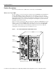
Product Descriptions What Is the Cisco 7010? The Cisco 7010 is a five-slot chassis, which uses the new RSP7000 (and the RSP7000CI), and provides up to three interface processor slots that can accommodate the following CxBus-based interface processors: Fast Ethernet, Ethernet, Token Ring, Fiber Distributed Data Interface (FDDI), channel attachment, multichannel, serial, and so forth.
Product Descriptions Storing the Cisco IOS images in Flash memory enables you to download and boot from upgraded Cisco IOS images remotely or from software images resident in the RSP7000 Flash memory, without having to remove and replace read-only memory (ROM) devices. Note The RSP7000 uses a software-controlled configuration register. There are no user-configurable jumpers on the RSP7000.
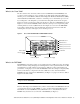
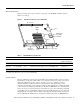
Product Descriptions Memory Components Figure 3 shows the various types of memory components on the RSP7000, and Table 1 lists the functions of each type.
Product Descriptions DRAM DRAM stores routing tables, protocols, and network accounting applications. The standard RSP7000 configuration is 16 megabytes (MB) of DRAM, with up to 128 MB available through single in-line memory module (SIMM) upgrades. Note When upgrading DRAM, you must use SIMMs from an approved vendor. To ensure that you obtain the most current vendor information, obtain the list from Cisco Information Online (CIO) or the Technical Assistance Center (TAC).
Installation Prerequisites Jumpers There are no user-configurable jumpers on the RSP7000. LEDs The two LEDs on the RSP7000 indicate the system and RSP7000 status. The normal LED is on when the system is operational. During normal operation, the CPU halt LED should be off. The CPU halt LED goes on only if the system detects a processor hardware failure.
Installation Prerequisites Electrical Equipment Follow these basic guidelines when working with any electrical equipment: • Before beginning any procedures requiring access to the chassis interior, locate the emergency power-off switch for the room in which you are working. • • • • Disconnect all power and external cables before moving a chassis.
Installation Prerequisites • When you remove a processor module, place it card side up on an antistatic surface or in a static shielding bag. Immediately place the module in a static shielding bag if you need to return it to the factory. • Avoid contact between electronic equipment and clothing. Antistatic straps only protect the equipment from ESD voltages on the body; ESD voltages on clothing can still cause damage. For safety, periodically check the resistance value of the antistatic strap.
Installation Prerequisites Caution All CxBus interface processors support OIR; however, you must shut down the system before removing or installing the RSP7000, which is a required system component. Removing an RSP7000 while the system is operating will cause the system to shut down or crash, and might damage or destroy memory files. Each RSP7000 and interface processor contains a bus connector with which it connects to the system backplane. The bus connector is a set of tiered pins, in three lengths.
Installation Prerequisites Software Prerequisites The RSP7000 is compatible with Cisco IOS Release 10.3(9), or later, Release 11.0(6), or later, or Release 11.1(1) or later. Cisco IOS Release 11.1(1) might require more than 16 MB of DRAM for your RSP7000; refer to the section “Replacing and Upgrading DRAM SIMMs” on page 29. The show version and show hardware commands display the current hardware configuration of the router, including the system software version that is currently loaded and running.
Installation Prerequisites Flash Memory Card Replacement and Formatting Prerequisites If you have a Flash memory card installed in the PCMCIA slot of your RP, you must reformat it if you want to use it with your new RSP7000. Using the RSP7000, you cannot read data on the RP’s Flash memory card, nor can you use it as bootable media. You must reformat the RP’s Flash card on the RSP7000 before you can use it with the RSP7000.
Installation Prerequisites Using the EXEC Command Interpreter Before you use the configure command, you must enter the privileged level of the EXEC command interpreter with the enable command. The system prompts you for a password if one has been set. The system prompt for the privileged level ends with a pound sign (#) instead of an angle bracket (>). At the console terminal, enter the privileged level as follows: Step 1 At the user-level EXEC prompt (>), enter the enable command.
Installation Prerequisites The following example shows the results of a failed ping: Sending 5, 100-byte ICMP Echos to 1.1.1.1, timeout is 2 seconds: ..... Success rate is 0 percent (0/5) Router# If the connection fails, check the physical connection to the remote file server and verify that you are using the correct address or name, then ping the server again.
Installation Prerequisites Step 4 Issue the write net (or copy startup-config tftp) command. The EXEC command interpreter prompts you for the name or interface processor address of the remote host that is to receive the configuration file. (The prompt might include the name or address of a default file server.) Router# write net Remote host []? Step 5 Enter the name or interface processor address of the remote host.
Installation Prerequisites Downloading (Retrieving) the Configuration File After you install the new RSP7000, you can retrieve the saved configuration and copy it to NVRAM. To retrieve the configuration, enter configuration mode and specify that you will configure the router from the network. The system prompts you for a host name and address, the name of the configuration file stored on the host, and confirmation to reboot using the remote file.
Installation Prerequisites Step 7 Before the system reboots with the new configuration, it displays the instructions you entered for confirmation. If the instructions are not correct, enter n (no) then press Return to cancel the process. To accept the instructions, press Return, or y then Return. Configure using router-confg from 1.1.1.1? [confirm] Booting router-confg from 1.1.1.
Installation Procedures Installation Procedures The following sections describe the procedures for installing or replacing processor modules. Before installing any new interfaces, ensure that your system meets the minimum software and microcode requirements described in the sections “Software Prerequisites” and “Microcode Prerequisites” on page 11. Note The OIR feature allows you to remove and install interface processors without turning off system power.
Installation Procedures Step 3 If you are replacing the RSP7000, disconnect any devices that are attached to the console or auxiliary ports. If you are removing the RSP7000 for maintenance and will reinstall the same one, you can leave the devices attached provided that doing so will not strain the cables. Step 4 Use a screwdriver (number 2 Phillips or 3/16-inch flat-blade) to loosen the two captive installation screws. (See Figure 4 on page 20.
Installation Procedures Note Figure 4 shows a typical processor module installation, and is not intended to indicate or recommend a particular slot location for the RSP7000.
Installation Procedures Step 4 While keeping the RSP7000 parallel to the backplane, carefully slide the carrier into the 7000 RSP slot until the RSP7000 faceplate makes contact with the ejector levers, then stop. (See Figure 4b.) Step 5 Using the thumb and forefinger of each hand to pinch each ejector, simultaneously push both ejectors inward (toward the handle) until they parallel to the faceplate. (See Figure 4c.
Installation Procedures Step 4 After the system boots the software and initializes the interface processors (approximately 30 seconds for systems with 16 MB of DRAM, and approximately 2 minutes for systems with 64 MB of DRAM), verify that the RSP7000 LEDs are in the following states: • • • RSP7000 normal LED is on CPU halt LED is off Boot error LED is off Step 5 Verify that all the enabled LEDs (on the interface processors) are on.
Troubleshooting the Installation Use the following procedure to format a new Flash memory card: Step 1 Insert the Flash memory card into slot 0. (If slot 0 is not available, use slot 1.) Step 2 To format the Flash memory card, use the format slot0: (or format slot1:) command as follows. (Use only Intel Series 2+ Flash memory cards.
Troubleshooting the Installation The slot 0 and slot 1 LEDs indicate which PCMCIA (Flash memory) card slot is in use, and each LED blinks when the card is accessed by the system. Note The RSP7000 is oriented horizontally in the Cisco 7010 router. Caution The reset switch (see Figure 5) resets the RSP7000 and the entire system. To prevent system errors and problems, use it only at the direction of your service representative.
Troubleshooting the Installation Interface Processor LEDs Each interface processor contains an enabled LED. The enabled LED goes on to indicate that the interface processor is operational and that it is powered up. It does not necessarily mean that the interface ports on the interface processors are functional or enabled. When the boot sequence is complete, all of the enabled LEDs should go on.
Troubleshooting the Installation Use the following startup sequences and troubleshooting procedures to isolate system problems: 1 When you restart up the system, the system power the DC LED (called the DC fail LED in the Cisco 7000 and the DC OK LED in the Cisco 7010) should not go on. — If the system power LED remains off, the RSP7000 is probably not fully inserted and connected to the backplane.
Troubleshooting the Installation 6 When the system boot is complete and all interface processors have been initialized, the console screen displays a script and system banner similar to the following: GS Software (RSP-K), Version 10.3(9) Copyright (c) 1986-1995 by Cisco Systems, Inc. Compiled Wed 10-May-95 11:06 — If all the previous conditions are met and this banner is displayed, the system startup was successful and your installation is complete.
Reference Information Reference Information Following is reference information for console and auxiliary port pinouts, replacing DRAM SIMMs, configuring the software configuration register, recovering a lost password, and using the front-panel PCMCIA slots for additional Flash memory. Console Port Signals The console port on the RSP7000 is an EIA/TIA-232, DCE, DB-25 receptacle. Both DSR and DCD are active when the system is running. The RTS signal tracks the state of the CTS input.
Reference Information Replacing and Upgrading DRAM SIMMs This section describes the steps for increasing the amount of DRAM by replacing up to four SIMMs that you obtain from an approved vendor. The system DRAM resides on up to four SIMMs on the RSP7000. The DRAM SIMM sockets are U4 and U12 for Bank 0, and U18 and U25 for Bank 1. The default DRAM configuration is 16 MB (two 8-MB SIMMs in Bank 0). (See Figure 6.) Note The total number of memory devices per SIMM differs for each manufacturer.
Reference Information Before proceeding, ensure that you have the proper tools and ESD-prevention equipment available. To upgrade DRAM, you install SIMMs in one or two banks. Table 4 lists the various configurations of DRAM SIMMs that are available. Note which banks are used given the combinations of available SIMM sizes and the maximum DRAM you require. SIMMs must be 60 ns or faster and no taller than one inch. Note Depending on your router configuration, Cisco IOS Release 11.
Reference Information Step 4 Release the spring clips from the SIMM that you wish to remove and release the SIMM from the socket. (See Figure 7.) Figure 7 Releasing the SIMM Spring Clips Faceplate edge of the system card Pull the tabs away with your thumbs, bracing your forefingers against the posts. Raise the SIMM to a vertical position.
Reference Information Installing New SIMMs SIMMs are sensitive components that are susceptible to ESD damage. Handle SIMMs by the edges only; avoid touching the memory modules, pins, or traces (the metal fingers along the connector edge of the SIMM).(See Figure 8.) Handling a SIMM H2326 Figure 8 Caution Handle SIMMs by the card edges only. SIMMs are sensitive components that can be shorted by mishandling.
Reference Information This completes the SIMM replacement procedure. Proceed to the section “Replacing the RSP7000” on page 19 to replace the RSP7000 in the chassis and restart the system for an installation check. If the system fails to boot properly, or if the console terminal displays a checksum or memory error, check the following: • Ensure that all SIMMs are installed correctly. If necessary, shut down the system and remove the RSP7000.
Reference Information Table 5 Software Configuration Register Bit Meanings Bit Number1 Hexadecimal Meaning 00 to 03 0x0000 to 0x000F Boot field (see Table 6) 06 0x0040 Causes system software to ignore NVRAM contents 07 0x0080 OEM bit enabled2 08 0x0100 Break disabled 09 0x0200 Use secondary bootstrap 10 0x0400 Internet Protocol (IP) broadcast with all zeros 11 to 12 0x0800 to 0x1000 Console line speed (default is 9600 baud) 13 0x2000 Boot default Flash software if network boot f
Reference Information Step 5 To display the configuration register value currently in effect and the value that will be used at the next reload, enter the show version EXEC command. The value will be displayed on the last line of the screen display, as in the example following: Configuration register is 0x141 (will be 0x101 at next reload) Step 6 Reboot the router. The new value takes effect.
Reference Information Table 7 Default Boot Filenames Action/File Name Bit 3 Bit 2 Bit 1 Bit 0 Bootstrap mode 0 0 0 0 Default software 0 0 0 1 cisco2-RSP 0 0 1 0 cisco3-RSP 0 0 1 1 cisco4-RSP 0 1 0 0 cisco5-RSP 0 1 0 1 cisco6-RSP 0 1 1 0 cisco7-RSP 0 1 1 1 cisco10-RSP 1 0 0 0 cisco11-RSP 1 0 0 1 cisco12-RSP 1 0 1 0 cisco13-RSP 1 0 1 1 cisco14-RSP 1 1 0 0 cisco15-RSP 1 1 0 1 cisco16-RSP 1 1 1 0 cisco17-RSP 1 1 1 1 Bit 8 co
Reference Information Table 9 System Console Terminal Baud Rate Settings Baud Bit 12 Bit 11 9600 0 0 4800 0 1 1200 1 0 2400 1 1 Bit 13 determines the server response to a bootload failure. Setting bit 13 causes the server to load operating software from Flash memory after five unsuccessful attempts to load a boot file from the network. Clearing bit 13 causes the server to continue attempting to load a boot file from the network indefinitely. By factory default, bit 13 is cleared to 0.
Reference Information Following are additional commands related to the Flash memory on the RSP7000 and the Flash memory cards.
Reference Information Recovering a Lost Password An overview of recovering a lost password follows: • • • Enter the show version command to note the existing software configuration register value. Break to the bootstrap program prompt. Change the configuration register to ignore NVRAM. Note A key to recovering a lost password is to set the configuration register so that the contents of NVRAM are ignored (0x0040), allowing you to see your password. • • • Enter privileged level in the system EXEC.
Reference Information Configuration Summary enabled are: console baud: 9600 boot: image specified by the boot system command or default to: cisco2-RSP do you wish to change the configuration? y/n [n] You must reset or power cycle for the new config to take effect Step 7 Initialize the router by entering the i command as follows: rommon 1 > i The router will power cycle, the configuration register will be set to ignore the configuration file, and the router will boot the boot system image and prompt you w
Reference Information Replacing a Flash Memory Card It might become necessary for you to replace or install a Flash memory card in your RSP7000. The RSP7000 has two PCMCIA slots: slot 0 (left) and slot 1 (right). (See Figure 9 on the following page.) The following procedure is generic and can be used for a Flash memory card in either slot position. A Flash memory card can be inserted and removed with the power on.
Reference Information Step 2 Insert the card into the appropriate slot until the card completely seats in the connector at the back of the slot and the eject button pops out toward you (See Figure 9b.) Note that the card does not insert all the way inside the RSP7000; a portion of the card will remain outside the slot. Do not attempt to force the card past this point. Step 3 To eject a card, press the appropriate ejector button until the card is free of the connector at the back of the slot.
Reference Information Copying a Bootable Image into a Flash Memory Card With the Flash memory card formatted, you can now copy a bootable image into it.
Reference Information Step 3 To enable the router, copy the image new.image to the Flash memory card, make this image in the Flash memory card (in slot 0) the default boot image, and reboot the router, use the following series of commands: Router> en Password: Router# copy tftp:new.image slot0:new.image 20575008 bytes available on device slot0, proceed? [confirm] Address or name of remote host [1.1.1.1]? Loading new.image from 1.1.1.
Reference Information Copying Bootable Images Between Flash Memory Cards As future releases of Cisco IOS images become available, you will receive these images either as a netbooted file, a file on floppy disk, or a file on a Flash memory card. The following scenario describes how to use a newly released image on a Flash memory card, in a system that has an older image on a Flash memory card in slot 0 (and a default boot image in the onboard Flash SIMM).
Reference Information Step 5 Use the following series of commands to designate the file image.new (which is in the Flash memory card in slot 0) as the default boot image: Router# config t Router(config)# no boot system Router(config)# boot system flash slot0:image.new Router(config)# ^z Router# copy running-config startup-config Router# reload When the system reloads, it will boot the file image.new from the Flash memory card in slot 0.
Cisco Information Online Cisco Information Online Cisco Information Online (CIO), is Cisco Systems’ primary, real-time support channel. Maintenance customers and partners can self-register on CIO to obtain additional content and services. Available 24 hours a day, 7 days a week, CIO provides a wealth of standard and value-added services to Cisco’s customers and business partners.
Cisco Information Online 48 7000 Series Route Switch Processor (RSP7000) Installation and Configuration in the Cisco 7000 Series Routers