
Router Getting Started Guide


3-46
Cisco IOS XR Getting Started Guide
OL-10957-02
Chapter 3 Bringing Up the Cisco IOS XR Software on a Multishelf System
Verifying Fabric Cabling Connections
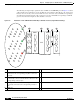
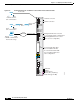
The following description helps explain the states of LEDs on the OIM LED panel. In Figure 3-6, fabric
cables should connect an LCC S13 card to the FCC S2 card as follows: A0 to J0, A1 to J1, and A2 to J2.
Instead, A1 is incorrectly connected to J2. This incorrect connection causes the LED corresponding to
J2 to blink red, indicating that the cable connection is incorrect. The LED corresponding to J1 blinks
green to show where the misplaced cable should be connected.
Figure 3-6 Illustration of How OIM LED Panel LEDs Map to Bundles and Slots (Single-Module Cabling)
1 OIM LED card 6 S13 card—This card is installed in an LCC.
2 Solid green LED—Indicates that the fabric cable
connected to the corresponding port (J0) is connected
correctly.
7 Correct fabric cable connection between FCC and LCC.
3 Flashing green LED—Indicates that a single fabric cable
is incorrectly connected and should be connected to the
corresponding connector (J1).
8 Incorrect fabric cable connection between FCC and LCC.
4 Flashing red LED—Indicates that a single fabric cable is
incorrectly connected to the corresponding connector
(J2).
9 Fabric card chassis
5 OIM card
3
4
138285
A0
A1
A2
J0
J1
J2
OIM0
J0
J1
J2
OIM11
1
2
3
4
5
6
7
8
9
10
11
12
1
2
3
4
5
6
7
8
9
10
11
12
1
2
3
4
5
6
7
8
9
10
11
12
1
5
6
9
10
0
1
2
3
4
5
6
7
8
9
10
11
0
1
2
3
4
5
6
7
8
9
10
11
0
1
2
3
4
5
6
7
8
9
10
11
2
3
4
1 9 5 6
7
8