
Router Quick Start Guide


20
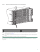
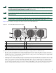
Figure 14 DC Power Supply Terminal Block
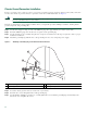
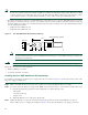
Caution Before you continue to install the terminal block ground wires, stop and perform Step 5. To prevent any contact
with metal lead on the ground wire and the plastic cover.
Step 3 You must wrap the positive and negative lead cables with sleeving. Take each lead wire and cover the area from the lug
to the wire with heavy shrink sleeving (see Figure 15, item 3).
1
DC power supply terminal block negative stud
3
Terminal block slotted keyed area
2
DC power supply terminal block positive stud
4
DC power supply terminal block plastic cover
This unit might have mo
re than one power supply connection. All connections must be
remov
OFF
55
-48/-60V 40A
280027
3
4
1
2