
Router Quick Start Guide


12
Chassis Ground Connection Installation
Before you connect power or turn on power to your router, you must provide an adequate chassis ground (earth) connection
for the router chassis. A ground connector is provided on each Cisco ASR 1006 Router. See Figure 7.
Caution The dual-lug chassis stud must be installed, the SIP and SPA must be fully inserted and screwed in and earthed to
prevent a potential hazard in a telecom line.
Have the recommended tools and supplies available before you begin this procedure: Phillips screwdriver, dual-lug chassis
ground component, and grounding wire.
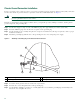
Step 1 Use the wire stripper to strip one end of the AWG #6 gauge wire approximately 0.75 inches (19.05 mm).
Step 2 Insert the AWG #6 gauge wire into the wire receptacle on the grounding lug.
Step 3 Use the crimping tool to carefully crimp the wire receptacle around the wire; this step is required to ensure a proper
mechanical connection.
Step 4 Attach the grounding lug with the wire so the grounding wire does not overlap the power supply.
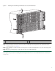
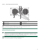
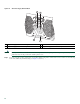
Figure 7 Attaching a Grounding Lug to the Chassis Ground Connector
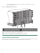
Step 5 Locate the chassis ground connector on the side of your chassis.
Step 6 Insert the two screws through the holes in the grounding lug.
Step 7 Use the Number 2 Phillips screwdriver to carefully tighten the screws until the grounding lug is held firmly to the
chassis. Do not overtighten the screws.
1
Chassis earth ground studs and lead wire
3
Earth ground connector on the chassis
2
Grounding screws
4
Earth ground symbol
280034
3
4
2
1